Method for creating topographical patterns in polymers via surface energy patterned films and the marangoni effect

a topographical pattern and surface energy patterned technology, applied in the field of light-based patterning methods, can solve the problems of limiting the throughput of these techniques, prohibitively expensive equipment and techniques, and high-resolution e-beam lithography techniques, though very precise, and are too slow for high-volume commercial applications

Active Publication Date: 2014-02-27
BOARD OF RGT THE UNIV OF TEXAS SYST
View PDF1 Cites 5 Cited by
  • Summary
  • Abstract
  • Description
  • Claims
  • Application Information

AI Technical Summary

Benefits of technology

[0011]In an embodiment, a method of forming a pattern in a polymer substrate includes: exposing the solid polymer substrate to a pattern of activating light for a time sufficient to cause at least a portion of the polymer substrate to undergo a chemical change in the solid state; and heating the polymer substrate to a temperature sufficient to liquify the polymer substrate after exposure to activating light, wherein the temperature is selected such that the polymer substrate adopts a configuration that corresponds to the pattern of activating light. In some embodiments, the polymer substrate is a thin film deposited on a substrate. The polymer substrate, in some embodiments, includes a mixture of a polymer and one or more photosensitizers. Alternatively, or in addition, the polymer substrate includes a polymer coupled to one or more photosensitizers. After the polymer substrate has been heated the polymer may be solidified by cooling the polymer substrate. In an alternate embodiment, the polymer may be solidified by crosslinking the polymer.

Problems solved by technology

Such processes lead to extremely complicated equipment and techniques that may be prohibitively expensive.
It is also believed that high-resolution e-beam lithography techniques, though very precise, are too slow for high-volume commercial applications.
The requirement of a mask during this step, inherently limits the throughput of these techniques.

Method used


Image

  • Method for creating topographical patterns in polymers via surface energy patterned films and the marangoni effect
  • Method for creating topographical patterns in polymers via surface energy patterned films and the marangoni effect
  • Method for creating topographical patterns in polymers via surface energy patterned films and the marangoni effect

Examples


Embodiment Construction

[0049]It is to be understood the present invention is not limited to particular devices or methods, which may, of course, vary. It is also to be understood that the terminology used herein is for the purpose of describing particular embodiments only, and is not intended to be limiting. As used in this specification and the appended claims, the singular forms “a”, “an”, and “the” include singular and plural referents unless the content clearly dictates otherwise. Furthermore, the word “may” is used throughout this application in a permissive sense (i.e., having the potential to, being able to), not in a mandatory sense (i.e., must). The term “include,” and derivations thereof, mean “including, but not limited to.” The term “coupled” means directly or indirectly connected.

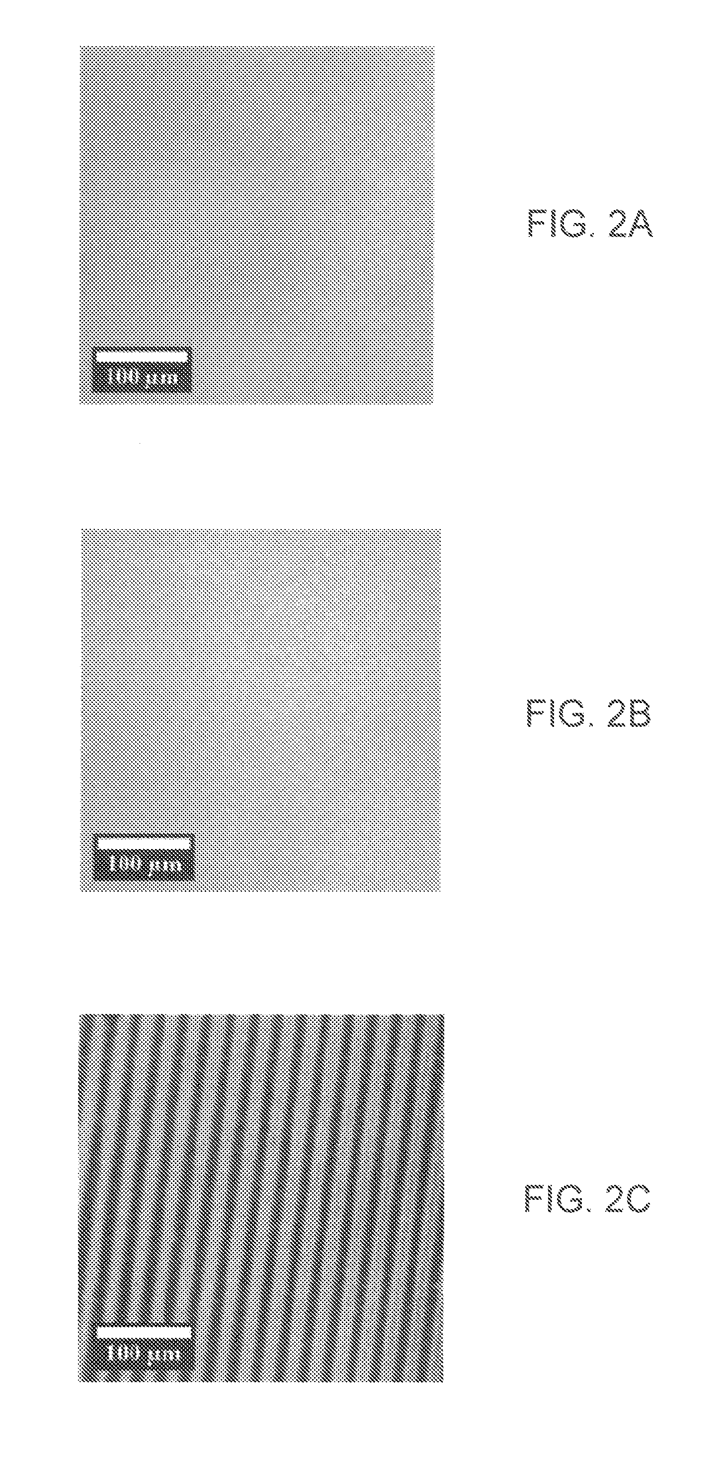
[0050]Small variations in temperature or composition at a fluid interface, often spontaneously generated, can cause local changes in surface tension and promote dramatic movement of the fluid. This phenomenon, referr...


PUM

PropertyMeasurementUnit
wavelengthsaaaaaaaaaa
wavelengthaaaaaaaaaa
thickaaaaaaaaaa

Abstract

Using a broadband light source and a photomask, surface energy gradients can be directly transferred into polymer films. The Marangoni effect causes high surface energy regions to rise upon heating the film. This leads to the formation of three-dimensional topography that can be locked in by quenching the polymer by cooling.

Description

PRIORITY CLAIM[0001]This application claims the benefit of U.S. Provisional Application No. 61 / 692,088 filed on Aug. 22, 2012.STATEMENT REGARDING FEDERALLY SPONSORED RESEARCH OR DEVELOPMENT[0002]This invention was made with government support from the National Science Foundation (NSF), Grant number DMR-1053293. The U.S. Government has certain rights to this invention.BACKGROUND OF THE INVENTION[0003]1. Field of the Invention[0004]The invention generally relates to patterning of polymeric materials. More specifically, the invention relates to light based patterning methods.[0005]2. Description of the Relevant Art[0006]Optical lithography techniques are currently used to alter topographies of many different surfaces. For example, sub-micron scale lithography has been a critical process in the microelectronics industry. Other applications of nanometer scale lithography exist in the areas of opto-electronics and magnetic storage. For example, photonic crystals and high-density patterned...

Claims


Application Information

Patent Timeline
Patent Type & Authority Applications(United States)
IPC IPC(8): G03F7/26B29C59/02
CPCB29C59/02G03F7/26G03F7/0002G03F7/36G03F7/38Y10T428/24802
Inventor ELLISON, CHRISTOPHER J.KATZENSTEIN, JOSHUA M.JANES, DUSTIN W.
Owner BOARD OF RGT THE UNIV OF TEXAS SYST
Why Eureka
Try Eureka