
Control cable

a control cable and light weight technology, applied in the direction of linear movement shafts, shafts, shafts, etc., can solve the problems of insufficient flexibility, achieve excellent buckling resistance, reduce weight, and suppress the transmissibility of vibrations.

Inactive Publication Date: 2014-02-20
HI-LEX CORPORATION
View PDF12 Cites 12 Cited by
  • Summary
  • Abstract
  • Description
  • Claims
  • Application Information

AI Technical Summary

Benefits of technology

The present invention relates to a wire used in an outer casing of a cable connector. The wire is made of an aluminum alloy, which results in weight reduction. The wire is twisted at a high speed to prevent vibration transmission. The wire has a polygonal cross section, providing excellent resistance to buckling. The covering layer formed of a coating material has a high tensile strength, further improving the buckling resistance. In case of an Al-Mg alloy or an Al-Mg-Si alloy, the diameter of the wire can be easily reduced and twisted, leading to better buckling resistance.

Problems solved by technology

In the above-described Patent Literature 1, with an outer casing in which a carbon steel oil tempered wire and a hard steel wire are disposed alternately in parallel, adhering to each other, and are helically twisted around the periphery of the flexible inner tube in a slack manner, the flexibility is insufficient.

Method used


Image

  • Control cable
  • Control cable
  • Control cable

Examples


example 1

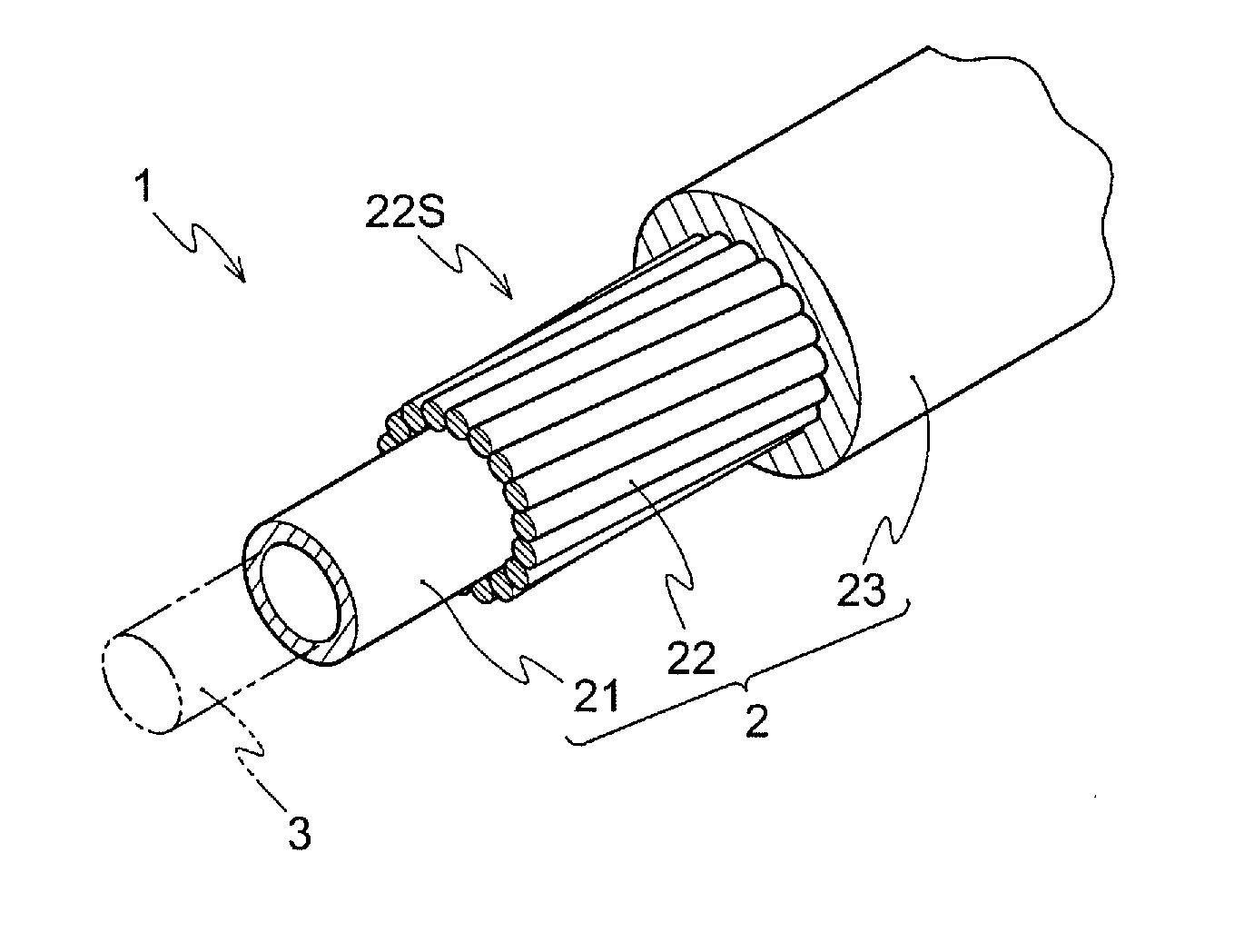
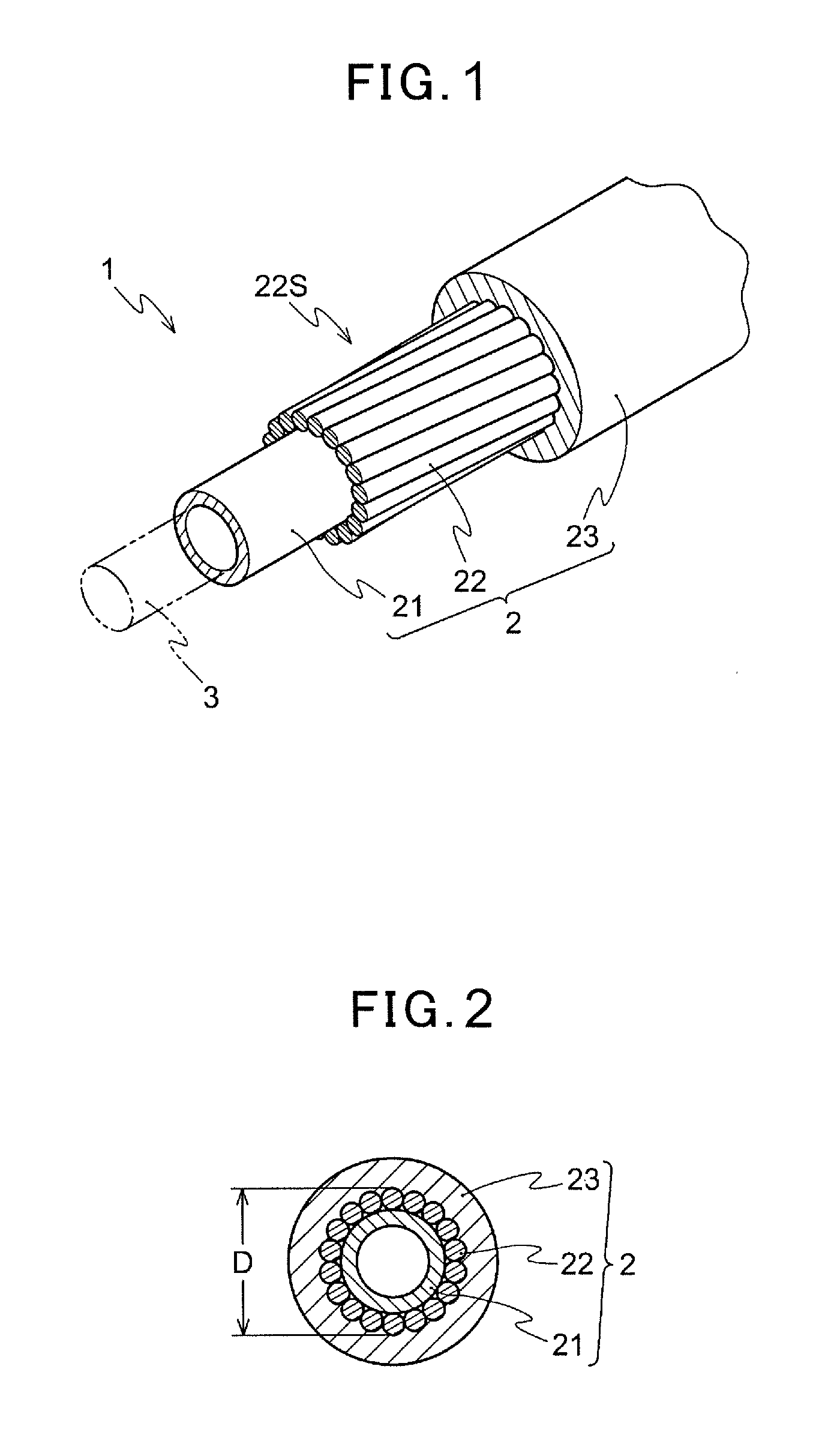
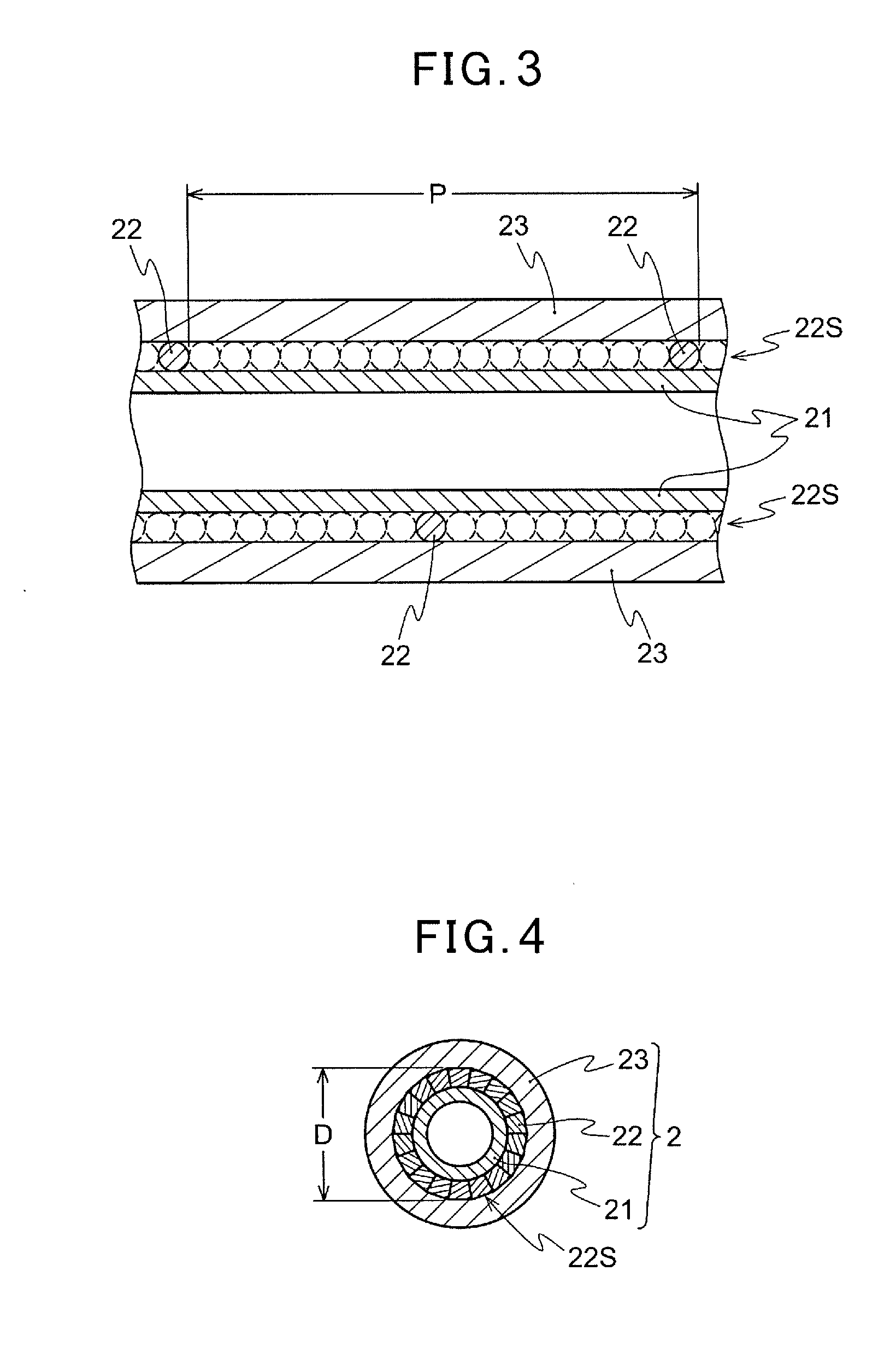
[0053]21 wires 22 of an Al—Mg alloy (5056) having a circular cross-sectional shape (0.7 mm in diameter) are helically twisted around the polyethylene liner 21 having thickness of 0.5 ram and an outer diameter of 4.2 mm. The wires are twisted such that an outer diameter of a shield D is 4.90 ram and the pitch P is 50 mm (a pitch magnification of 10.2). Subsequently, the covering layer 23 is formed by covering the shield layer 22S with a polypropylene having the tensile strength of 20 MPa (ZELAS (registered trademark) of Mitsubishi Chemical Corporation: flexural modulus of 630 MPa defined in ASTM D790) to form the outer casing 2 of the control cable 1 having an outer diameter of 7 mm and of a type illustrated in FIG. 1 (and FIG. 2).

[0054]The vibration damping characteristic, the crushing strength, and the weight reduction index are studied for the manufactured outer casing 2. The results are illustrated in Table 1.

examples 2 to 15

[0055]Examples 2 to 15 are the same as Example 1 except for the type, the cross-sectional shape, the size, and the number of the wires 22 and the material of the covering layer 23, which are changed as illustrated in Table 1. An outer casing 2 having the same outer diameter, the outer diameter of the shield D, the pitch P, and the pitch magnification as illustrated in Table 1 is manufactured. The vibration damping characteristic, the crushing strength, and the weight reduction index are studied in the same way as Example 1. The results are illustrated in Table 1.

[0056]Note that the following materials are described in Table 1.

(Aluminum Alloy)

[0057]5056: Al—Mg alloy defined in JIS H4040 having the tensile strength of 439 MPa

6063: Al—Mg—Si alloy defined in JIS H4040 having the tensile strength of 380 MPa

(Covering Layer)

[0058]PP: ZELAS (registered trademark) from Mitsubishi Chemical Corporation having the tensile strength of 20 MPa and the flexural modulus of 630 MPa

TPEE (1): polyester...


PUM


Abstract

An object of the present invention is to provide a control cable having an outer casing provided with helically twisted metallic wires. The outer casing is light-weight, has a satisfactory buckling resistance, and can suspend generation of a vibrational noise. A control cable (1) is provided with an outer casing (2) and an inner cable (3). The outer casing (2) is provided with a liner (21), a plurality of wires (22) helically twisted around the liner (21), and a covering layer (23) formed on an outer side of the wires (22) in a radial direction of the outer casing (2). The material of the wires (22) is an aluminum alloy, and the pitch of the wires (22) is 10 to 35 times an outer diameter of a shield.

Description

TECHNICAL FIELD[0001]The present invention relates to a light-weight control cable with which transmission of a vibration can be suppressed.BACKGROUND ART[0002]As a conventional control cable, as illustrated in FIG. 10, a control cable has been disclosed in which an outer casing 100 is used. The outer casing 100 has a flexible inner tube 101, and around a periphery thereof, a plurality of oil tempered wires 102 and a plurality of easily-flexed wires 103 are helically twisted in a slack manner such that the wires are disposed in parallel, adhering, and adjacent to each other. On a periphery thereof, a synthetic resin covering layer 104 is formed (see Patent Literature 1).[0003]In the above-described Patent Literature 1, with an outer casing in which a carbon steel oil tempered wire and a hard steel wire are disposed alternately in parallel, adhering to each other, and are helically twisted around the periphery of the flexible inner tube in a slack manner, the flexibility is insuffici...

Claims


Application Information

Patent Timeline
Patent Type & Authority Applications(United States)
IPC IPC(8): F16C1/20
CPCF16C1/20F16C1/26Y10T74/20456
Inventor TSUDA, AKIRASAKAGUCHI, TOMO
Owner HI-LEX CORPORATION
Learn More