
Inverted cylindrical magnetron (ICM) system and methods of use

a technology of inverted cylindrical magnetron and magnetron, applied in the direction of electrolysis components, vacuum evaporation coatings, coatings, etc., can solve the problems of reducing the efficiency of the magnetic field, increasing the fabrication cost, and affecting the effect of the magnetic field line virtual anode formation

Active Publication Date: 2014-02-13
VACTRONIX SCI LLC
View PDF4 Cites 24 Cited by
  • Summary
  • Abstract
  • Description
  • Claims
  • Application Information

AI Technical Summary

Benefits of technology

The patent describes a system and method for an Inverted Cylindrical Magnetron. This device includes a process chamber with a central anode and two annular end anodes, which form a 3-anode configuration to provide uniform electric field. The system also includes a cathode, a target, and a plurality of multi-zone electromagnets or hybrid electro-permanent magnets which provide a tunable magnetic field. The technical effects of this system and method include improved uniformity of electric field, resulting in improved performance of the device.

Problems solved by technology

The so-called inverted cylindrical magnetron (ICM), in which the target is a cylinder eroded by the sputtering plasma at the inner surface, is more complicated in target geometry and bonding, and hence its greater fabrication cost.
However, such virtual anode forming along magnetic field lines is still inferior as the magnetic field lines are curved to cathode side towards two ends, and also the virtual anode is subject to operation conditions and actual hardware design.
Under some ICM operation conditions, plasma impedance can be quite high such that the electrical field uniformity is not as good as that with actual anode (made of metal: very low resistance).
Those electrical insulators are normally made of brazed ceramics-metal tubular structure, which will add alignment error and can still be subject to electrical short due to metallic deposits.
Conventional art ICM sources using metallic bonded target to copper tube is very expensive and has significant operation temperature limit due to lower melting point of bonding materials, which makes it almost impossible for high deposition rate applications.
For some applications that require specific target temperature control, copper construction may lead to temperature non-uniformity due to copper's very high heat conductivity and relatively lower heat capacitance.
The prior art of ICM magnetron uses permanent magnets and has only fixed magnetic field and inherently suffers from non-uniform target erosion and related film deposition non-uniformity.
Implementation of some motion mechanisms can help improve the uniformity to certain extent, but it creates hardware complexity and is still lacking easy magnetic field tunability, which cannot meet stringent requirements of high demanding applications such as ultra-precise stoichiometry control in medical device material deposition that exceeds known PVD film applications at over 1 um thickness range.
Conventional coil design applies a single zone solenoid coil and suffers non-uniform magnetic flux density along the axial direction.
And conventional ICM magnetron sputtering has fixed substrate-to-target distance per equipment design and it is normally not an available process-tuning knob.

Method used


Image

  • Inverted cylindrical magnetron (ICM) system and methods of use
  • Inverted cylindrical magnetron (ICM) system and methods of use
  • Inverted cylindrical magnetron (ICM) system and methods of use

Examples


Embodiment Construction

[0023]The foregoing and other features and advantages of the invention are apparent from the following detailed description of exemplary embodiments, read in conjunction with the accompanying drawings. The detailed description and drawings are merely illustrative of the invention rather than limiting, the scope of the invention being defined by the appended claims and equivalents thereof.

[0024]Generally speaking, the inverted cylindrical magnetron source (ICM), also known as hollow cathode magnetron source, and associated sputter deposition system are deployed for high throughput and precisely controlled uniform deposition of high purity cylindrical metallic thin films.

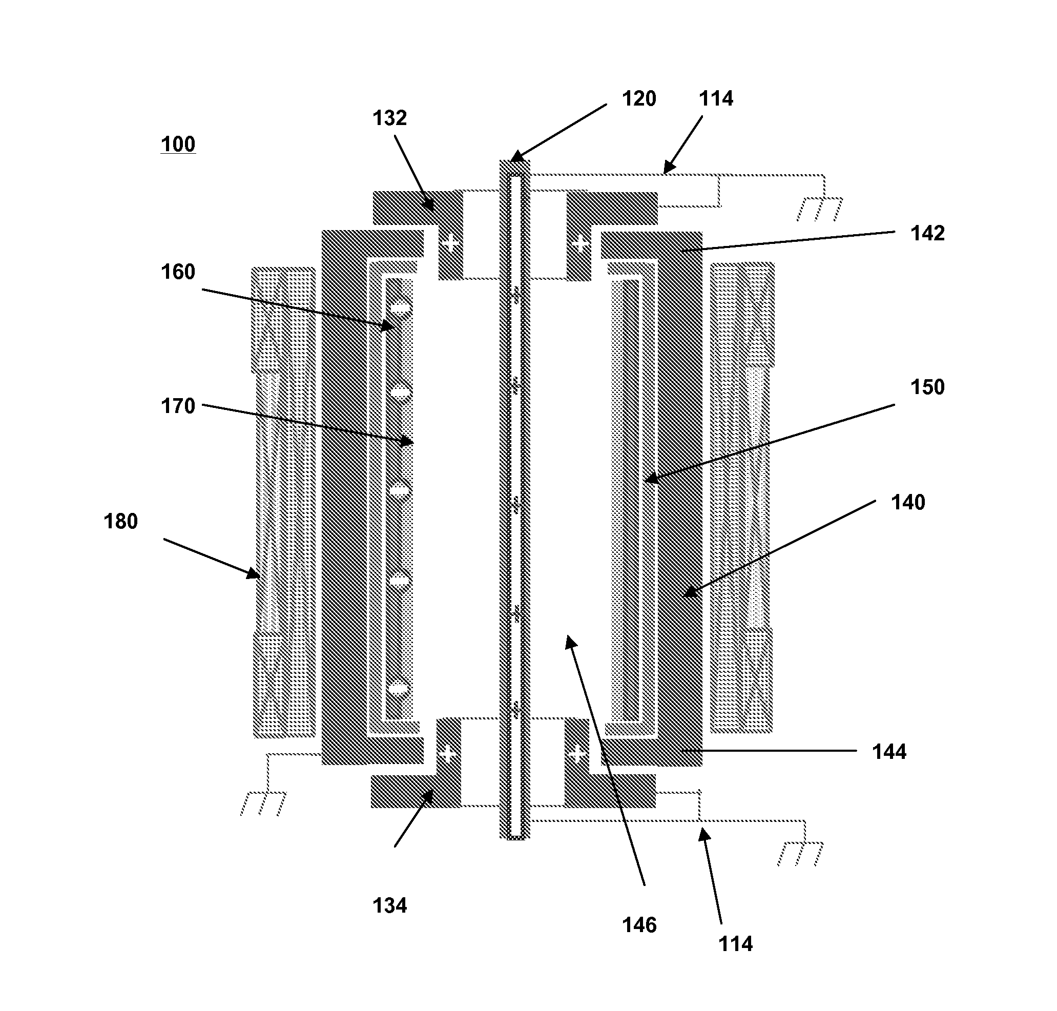
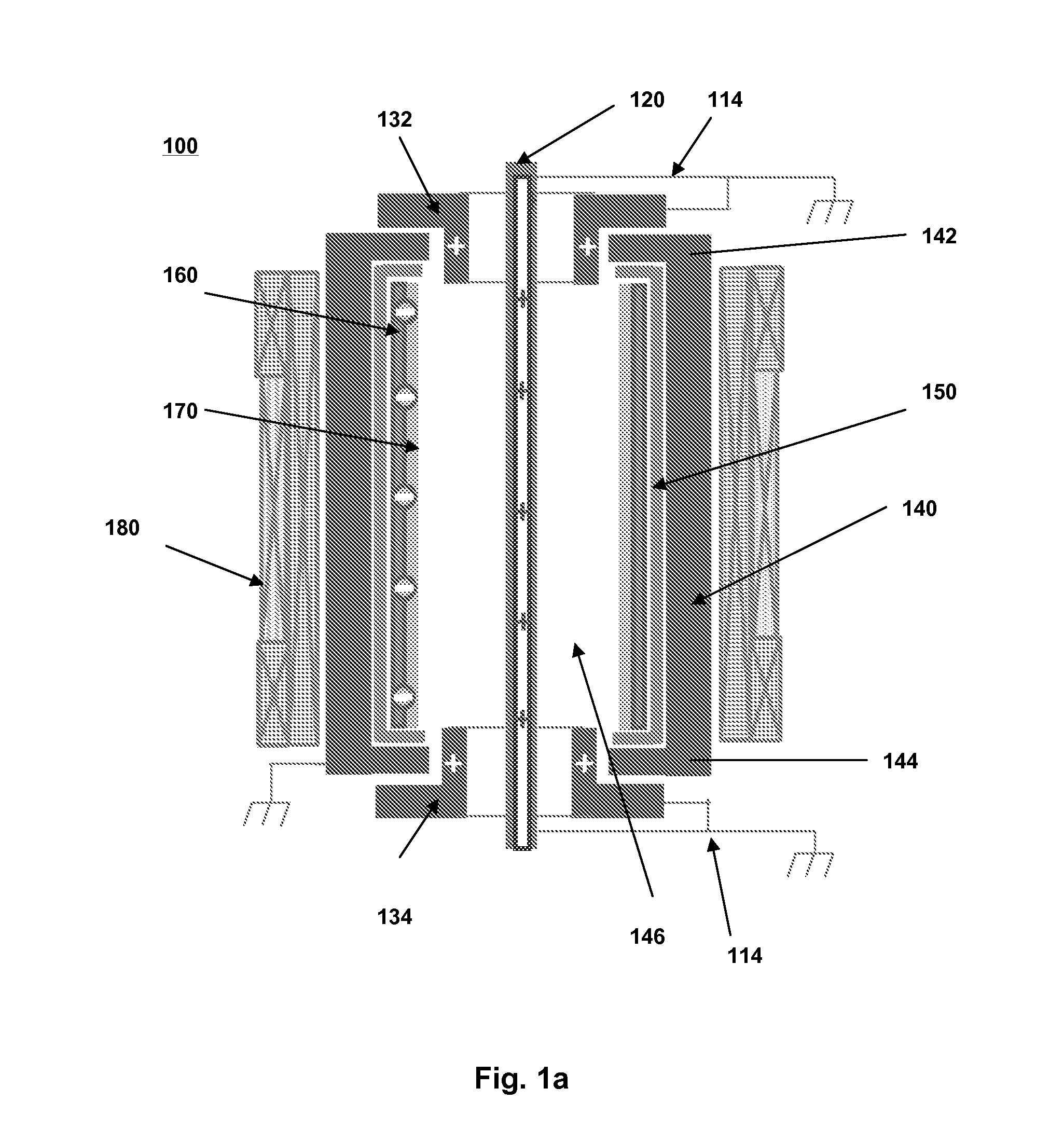
[0025]As shown in FIG. 1a, an inverted cylindrical magnetron (ICM) source 100 generally comprises a co-axial central anode 120 concentrically located within a first annular end anode 132 and a second annular end anode 134, which is the core of a cylindrical process chamber 320 including a top end 142 and a bottom end ...


PUM

PropertyMeasurementUnit
Fractionaaaaaaaaaa
Electric potential / voltageaaaaaaaaaa

Abstract

An Inverted Cylindrical Magnetron (ICM) System and Methods of Use is disclosed herein generally comprising a co-axial central anode concentrically located within a first annular end anode and a second annular end anode; a process chamber including a top end and a bottom end in which the first annular end anode and the second annular end anode are coaxially disposed, whereby the first annular end anode, the second annular end anode, and the central anode form a 3-anode configuration to provide electric field uniformity, and the process chamber including a central annular space coupled to a tube insulator disposed about the central annular space wall; a cathode concentrically coupled to the tube insulator and a target; and a plurality of multi-zone electromagnets or hybrid electro-permanent magnets surrounding the exterior of the process chamber providing a tunable magnetic field.

Description

CROSS-REFERENCE TO RELATED APPLICATIONS[0001]The present application claims priority to U.S. Provisional Patent Application Ser. No. 61 / 681,403, filed Aug. 9, 2012, which is hereby incorporated by reference in its entirety.BACKGROUND[0002]The invention generally relates to inverted cylindrical magnetron sources and the methods of use.[0003]The use of magnetron sputtering in the rapid deposition of metal films, reactively sputtered compound films and etching processes has found broad acceptance. The most-used type is the planar magnetron and its deposition profile and shown that the uniformity of the film thickness depends on the plasma sheath thickness and the magnetic field strength. The so-called inverted cylindrical magnetron (ICM), in which the target is a cylinder eroded by the sputtering plasma at the inner surface, is more complicated in target geometry and bonding, and hence its greater fabrication cost.[0004]In addition, conventional ICM sources are developed mainly for sin...

Claims


Application Information

Patent Timeline
IPC IPC(8): H01J23/02
CPCH01J23/02C23C14/35H01J37/3405H01J37/3417H01J37/342C23C14/566
Inventor XU, TIANZONGGUO, GEORGE XINSHENGNGUYEN, OANH
Owner VACTRONIX SCI LLC
Learn More