
Encapsulated Preformed Shapes

Inactive Publication Date: 2014-02-06
SPOKANE INDS
View PDF5 Cites 17 Cited by
  • Summary
  • Abstract
  • Description
  • Claims
  • Application Information

AI Technical Summary

Benefits of technology

The patent describes a method of making a composite component by integrating preformed ceramic shapes with a base metal. This helps stiffen the composite. The ceramic shapes can be arranged in layers to increase stiffness and reduce weight. Channels can be added to compartmentalize the ceramic shapes and increase the compression force on them during solidification of the base metal. These features make it possible to create robust and stiff composite components.

Problems solved by technology

However, these armor assemblies still have weaknesses.
For example, the armor assemblies may not be stiff enough to keep from deforming or deflecting during use.
Further, the armor assemblies may be relatively heavy as compared to armor assemblies using less metal.

Method used


Image

  • Encapsulated Preformed Shapes
  • Encapsulated Preformed Shapes
  • Encapsulated Preformed Shapes

Examples


example method

of Forming An Encapsulated Array With Barrier Layer Covered Tiles

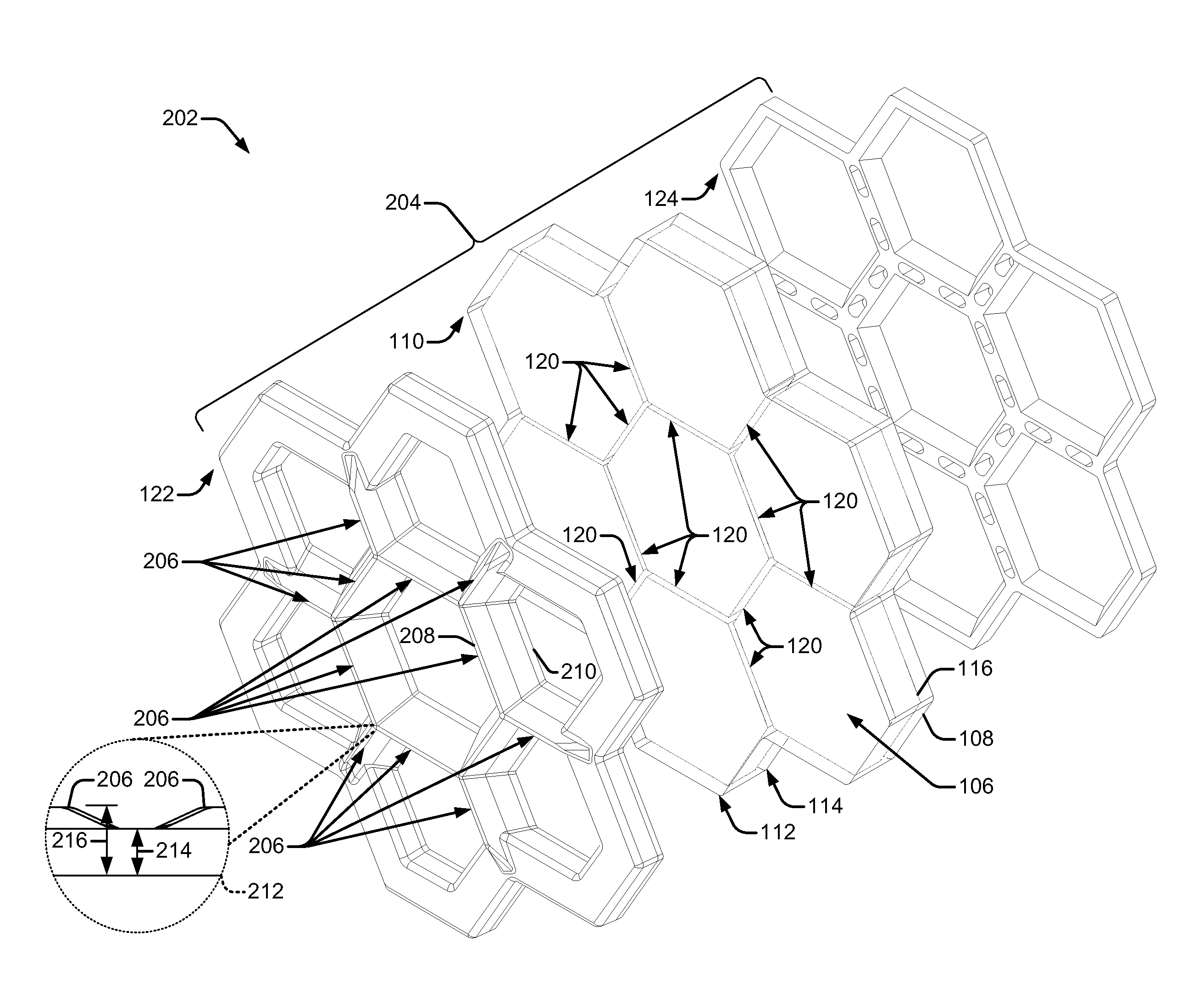
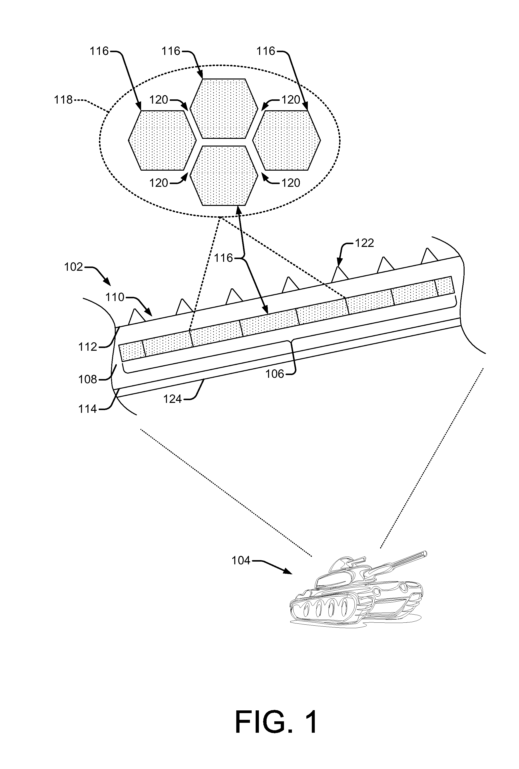
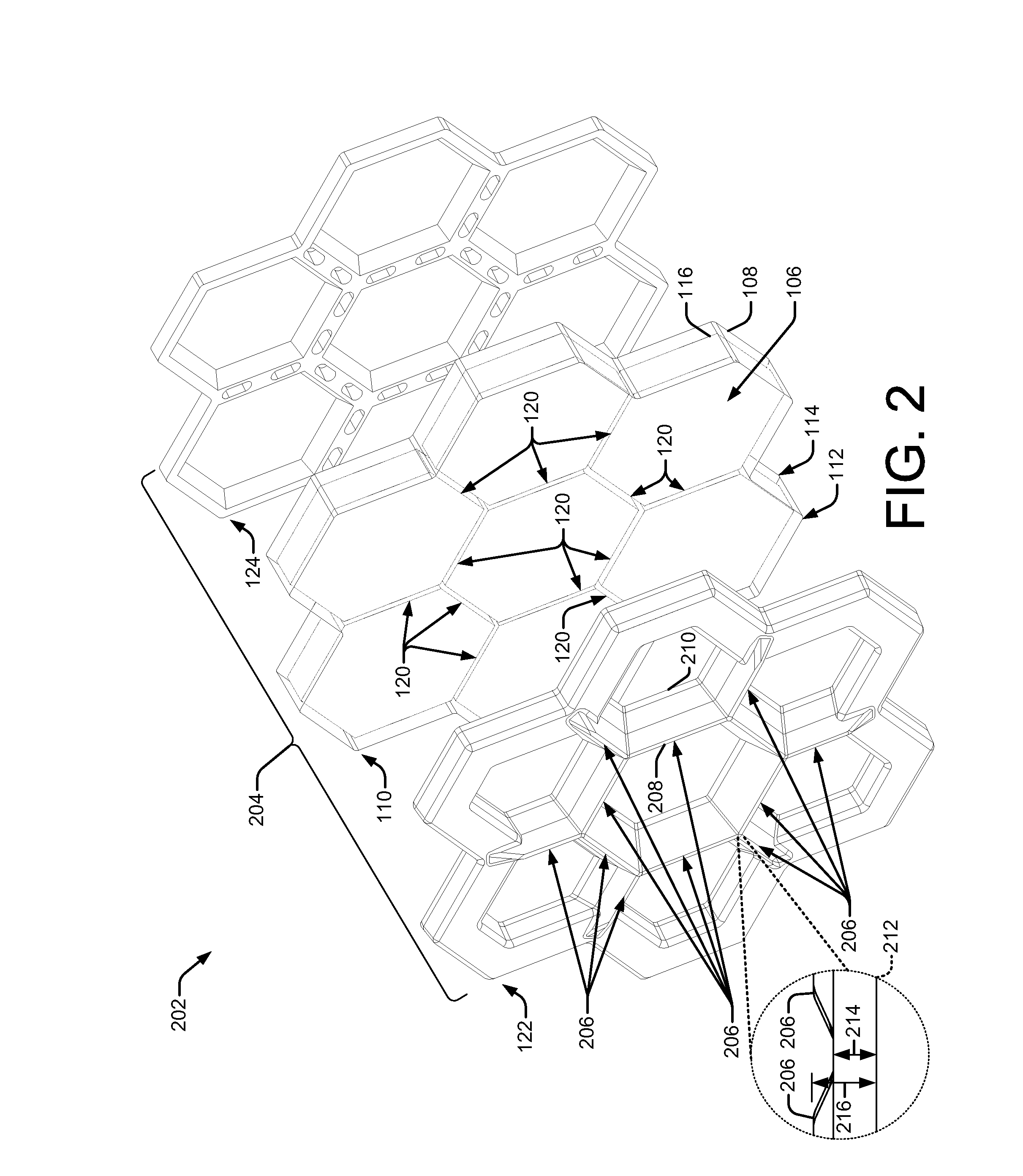
[0100]FIG. 10 illustrates an example process 1000 of manufacturing an encapsulated array (e.g., encapsulated array 110) with ceramic elements (e.g., ceramic elements 116) covered with a barrier layer (e.g., barrier layer 508), alongside corresponding schematic diagrams illustrating the operations being described in the process 1000. By way of example and not limitation, this process may be performed at a manufacturing facility, a plant, a foundry, a factory, or the like.

[0101]Process 1000 includes operation 1002, which represents covering (e.g., wrap, coat, enclose, etc.) each solid ceramic element in an array of solid ceramic elements (e.g., array of ceramic elements 106) with the barrier layer. For example, a foundry casting the array of solid ceramic elements may manually cover each ceramic element, or the foundry casting the array of solid ceramic elements may be provided with the ceramic elements already covered w...


PUM

PropertyMeasurementUnit
Diameteraaaaaaaaaa
Diameteraaaaaaaaaa
Lengthaaaaaaaaaa

Abstract

Anti-ballistic component including encapsulated preformed ceramic shapes are disclosed. Preformed ceramic shapes having a preformed geometry are encapsulated in a metal alloy to stiffen and lighten an anti-ballistic component. The preformed ceramic shapes may be arranged in layers of uniform arrays of preformed ceramic shapes and contained in a porous container to receive the metal alloy during a casting process. A truss structure may be integrated in the preformed ceramic shapes to compartmentalize the preformed ceramic shapes into multiple isolated sub regions to stiffen the anti-ballistic component.

Description

BACKGROUND[0001]Ballistic impact resistant components are desirable in a variety of industrial, commercial, and military applications.[0002]Recently, armor assemblies formed of multiple materials having different material properties (i.e., high hardness and toughness) have been used.[0003]However, these armor assemblies still have weaknesses. For example, the armor assemblies may not be stiff enough to keep from deforming or deflecting during use. Further, the armor assemblies may be relatively heavy as compared to armor assemblies using less metal.[0004]Thus, there remains a need to develop new armor assemblies that are stiffer and lighter.BRIEF SUMMARY[0005]This Brief Summary is provided to introduce simplified concepts relating to techniques for manufacturing anti-ballistic components, such as armor, comprising encapsulated preformed ceramic shapes, which are further described below in the Detailed Description. This Summary is not intended to identify essential features of the cl...

Claims


Application Information

Patent Timeline
IPC IPC(8): F41H5/02F41H5/04
CPCF41H5/0421F41H5/02F41H5/0492
Inventor GROZDANICH, ROD ALANKACZMAREK, EDWARD ROBERT
Owner SPOKANE INDS
Learn More