Airtight member and its production process

a technology of airtight parts and production processes, applied in the direction of layered products, doors/windows, chemistry apparatuses and processes, etc., can solve the problems of substrate reliability, strength decline at the sealing portion between glass substrates, etc., and achieve good reproducibility and reliability, the effect of increasing reliability

Inactive Publication Date: 2014-01-23
ASAHI GLASS CO LTD
View PDF5 Cites 13 Cited by
  • Summary
  • Abstract
  • Description
  • Claims
  • Application Information

AI Technical Summary

Benefits of technology

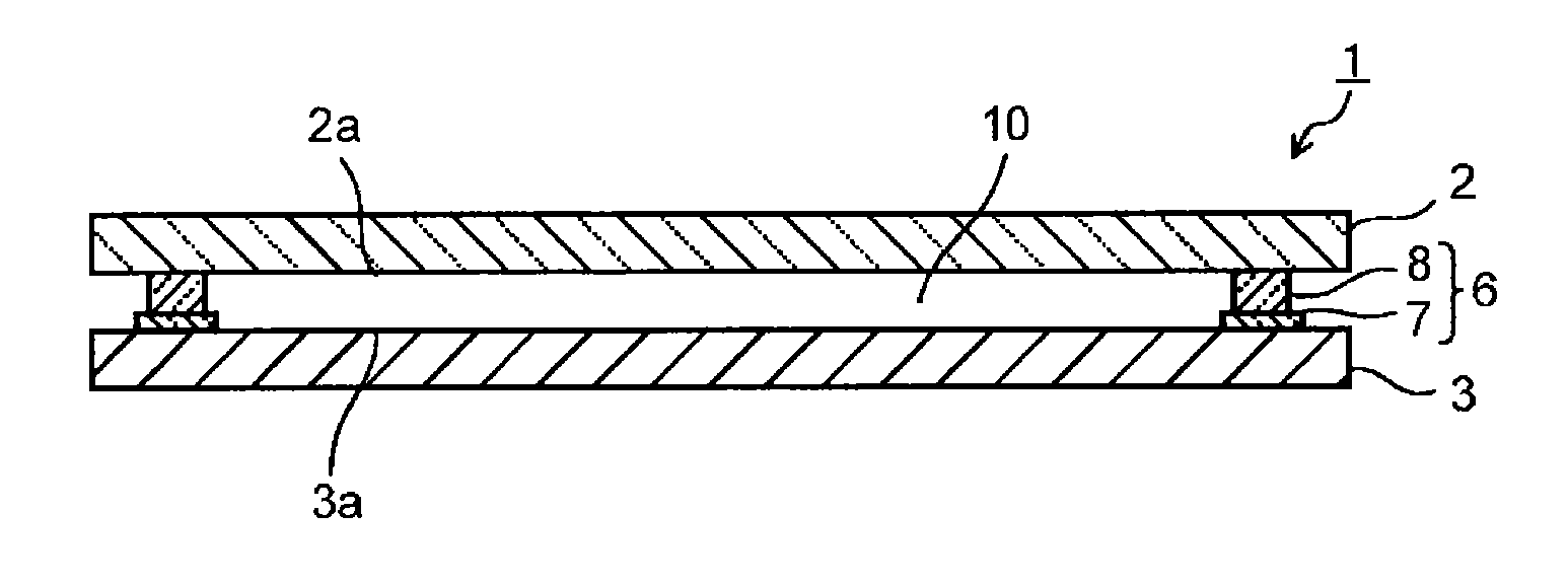
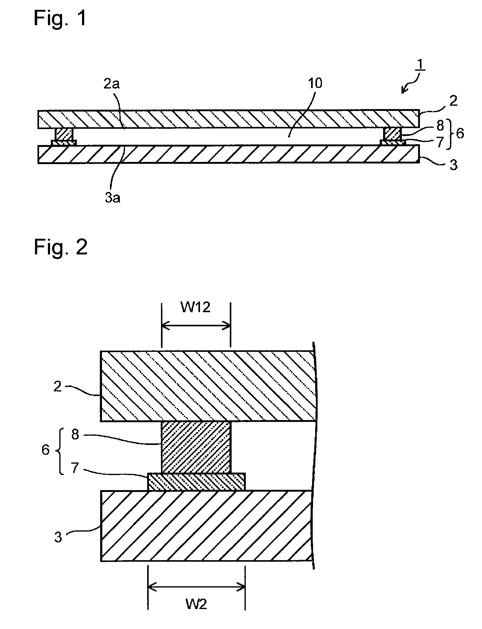
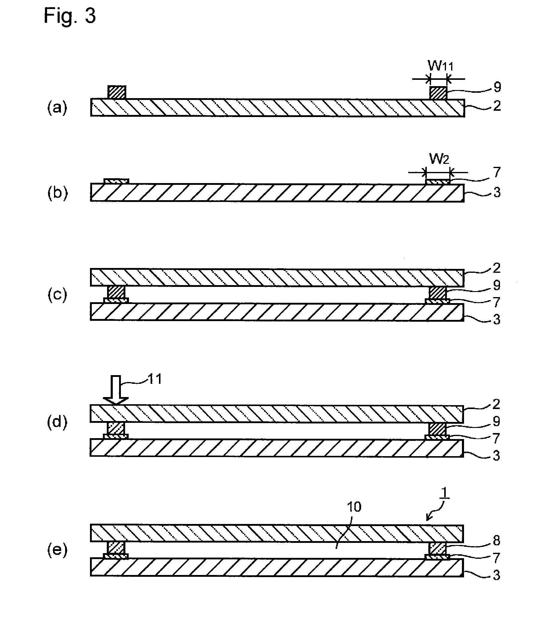
[0010]According to the airtight member and its production process of the present invention, when the space between a glass substrate and a highly thermally conductive substrate is airtightly sealed by employing local heating by electromagnetic waves, the bonding property of a sealing layer to the highly thermally conductive substrate and the reliability can be increased. Accordingly, an airtight member in which the space between a glass substrate and a highly thermally conductive substrate is airtightly sealed can be provided with good reproducibility and reliability.

Problems solved by technology

The stress applied to the glass substrate or the sealing layer may cause cracks or breakage to the sealing layer or the glass substrate, or may cause a decrease in the strength at the sealing portion between the glass substrate and the highly thermally conductive substrate and the reliability.

Method used


Image

  • Airtight member and its production process
  • Airtight member and its production process
  • Airtight member and its production process

Examples


example 1

[0062]First, bismuth glass frit (softening point: 410° C.) having a composition, as calculated as oxides, 83 mass % of Bi2O3, 5 mass % of B2O3, 11 mass % of ZnO and 1 mass % of Al2O3, and having an average particle size (D50) of 1.0 μm, a cordierite powder having an average particle size (D50) of 0.9 μm as a low expansion filler, and a laser absorber having a composition of Fe2O3—Al2O3—MnO—CuO and having an average particle size (D50) of 0.8 μm, were prepared. The average particle size was measured by using a laser diffraction / scattering particle size measuring apparatus (Microtrac HRA manufactured by NIKKISO CO., LTD.).

[0063]67.0 vol % of the bismuth glass frit, 19.1 vol % of the cordierite powder and 13.9 vol % of the laser absorber were mixed to prepare a glass material for sealing for a sealing material layer (hereinafter this will be referred to as low-melting glass material 1). Then, 80 mass % of the glass material for sealing and 20 mass % of a vehicle were mixed to prepare a...

examples 2 to 7

[0069]An airtight member was prepared in the same manner as in Example 1 except that the glass material for sealing, the glass material for forming a glass layer and the highly thermally conductive substrate as identified in Table 1 or 2 were used, and the conditions for producing the glass layer and the laser irradiation conditions as identified in Table 1 were employed. The outer appearance test and the airtightness test for the obtained airtight member were carried out in the same manner as in Example 1. The results are shown in Table 1.

[0070]In Table 1, the glass material 3 for forming a glass layer comprises glass frit having a composition comprising 55 mass % of SiO2, 3 mass % of B2O3, 11 mass % of CaO, 18 mass % of SrO, 10.5 mass % of BaO, 0.5 mass % of Na2O and 2 mass % of ZrO2, and contains no other filler. Further, the glass material 4 for forming a glass layer comprises glass frit having a composition comprising 27 mass % of SiO2, 9 mass % of B2O3 and 64 mass % of PbO, an...


PUM

PropertyMeasurementUnit
thicknessaaaaaaaaaa
arithmetic mean roughnessaaaaaaaaaa
coefficient of thermal conductivityaaaaaaaaaa

Abstract

To provide a process for producing an airtight member, which can improve bonding property of a sealing layer to a highly thermally conductive substrate and reliability, in airtight sealing of a space between a glass substrate and a highly thermally conductive substrate by local heating by electromagnetic waves.
A glass substrate having a sealing material layer having electromagnetic wave absorbing property provided on a sealing region, and a highly thermally conductive substrate having a glass layer formed on a sealing region, are laminated while the sealing material layer and the glass layer are brought into contact with each other. The sealing material layer is irradiated with electromagnetic waves through the glass substrate to heat and melt the sealing material layer thereby to bond it to the glass layer, so as to form a sealing layer which airtightly seals the space between the glass substrate and the thermally conductive substrate.

Description

TECHNICAL FIELD[0001]The present invention relates to an airtight member and its production process.BACKGROUND ART[0002]To a package in which an electronic element such as a quartz oscillator, a piezoelectric element, a filter element, a sensor element, an imaging element, an organic EL element or a solar battery element is airtightly sealed, for example, a package structure using a glass substrate for a base substrate on which the electronic element is to be formed or mounted, and using a highly thermally conductive substrate made of a metal material or ceramic material excellent in the heat dissipation property, for a cover substrate which airtightly seals the electronic element, has been applied. Further, to a package in which a light-receiving element such as an imaging element or a light-emitting element such as an organic EL element is airtightly sealed, e.g. a package structure using a highly thermally conductive substrate for a base substrate and using a transparent glass su...

Claims


Application Information

Patent Timeline
Patent Type & Authority Applications(United States)
IPC IPC(8): H05K5/06
CPCH05K5/06C03C3/072C03C3/089C03C3/122C03C8/04C03C8/10C03C27/044H03H9/1014H03H9/1071
Inventor KAWANAMI, SOHEIHISHINUMA, AKIHIRO
Owner ASAHI GLASS CO LTD
Why Eureka
Try Eureka