
Lens arrangement and illuminator housing

Inactive Publication Date: 2014-01-23
LEDIL
View PDF10 Cites 17 Cited by
  • Summary
  • Abstract
  • Description
  • Claims
  • Application Information

AI Technical Summary

Benefits of technology

The present invention provides an illuminator that can adjust the light pattern without changing the outer dimensions of the illuminator. This is achieved by the cooperating shapes of the exit convex surface of the first lens and the concave entry surface of the second lens. The illuminator can be used in places of commerce or in other applications such as a flashlight or bicycle lamp. The adjustment mechanism can be made by a simple rotation adjustment means or remote controlled manipulation means, providing flexibility in the installation and adjustment of the illuminator.

Problems solved by technology

However, while there is ample supply of LED illuminators for consumers, there is scarce supply of LED illuminators for providing lighting for places of commerce, such as jewelry stores.
However, U.S. Pat. No. 8,047,684 B2 provides no solution for establishing a source of an adjustable artificial which can be flush installed into furniture of a place of business, for example.
If the illuminator is fixed to the receiving structure from the outmost lens housing, the light pattern cannot be adjusted.
Albeit providing an adjustable light beam, the illuminator disclosed in U.S. Pat. No. 8,047,684 B2 is for reasons given above unsuitable for flush installation and therefore unsuitable for most commercial applications.
However, by rotating adjustment motion, the size of the device of WO 2006 / 072885 A1 varies also making it unsuitable for most commercial applications as explained above.

Method used


Image

  • Lens arrangement and illuminator housing
  • Lens arrangement and illuminator housing
  • Lens arrangement and illuminator housing

Examples


Embodiment Construction

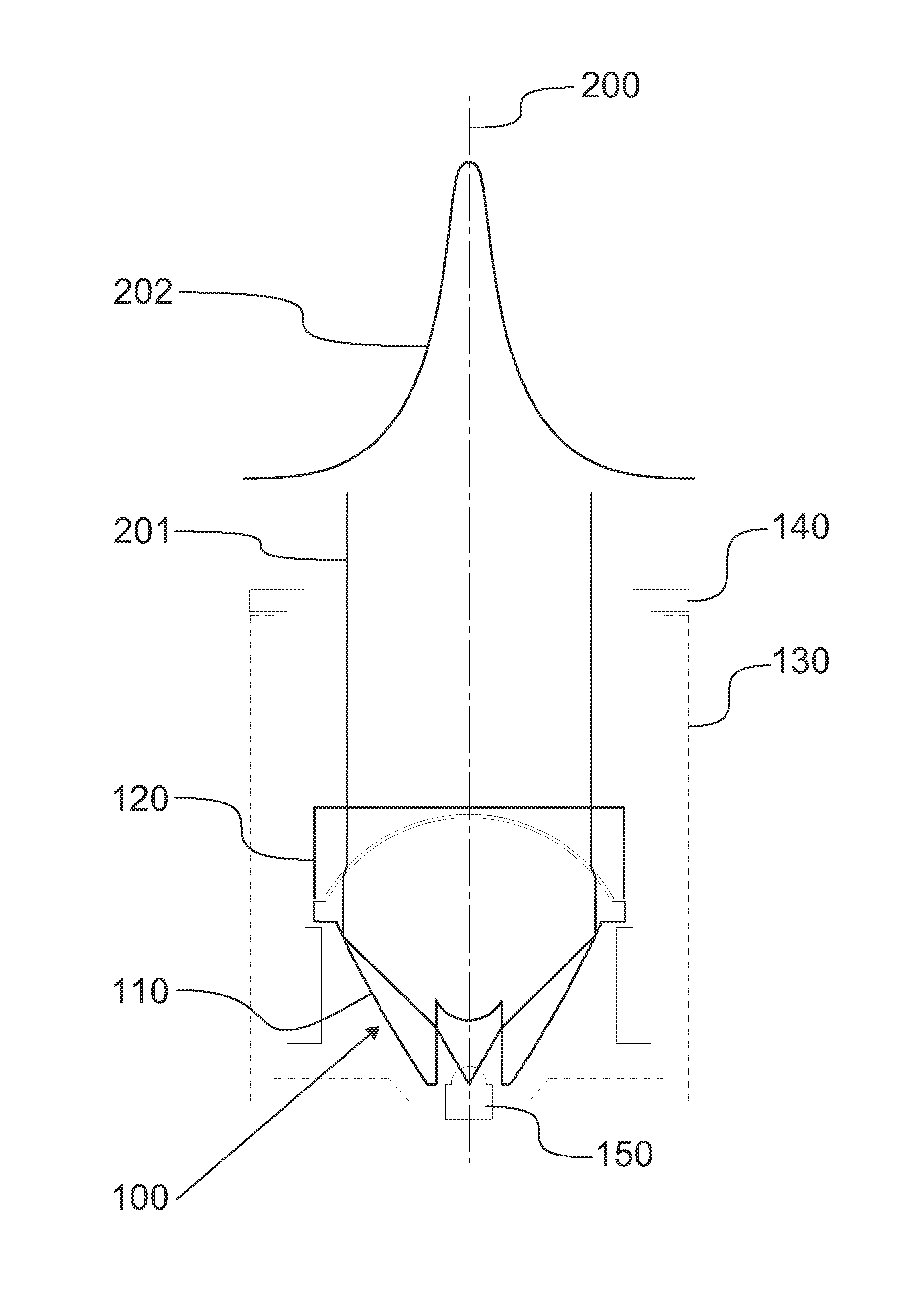
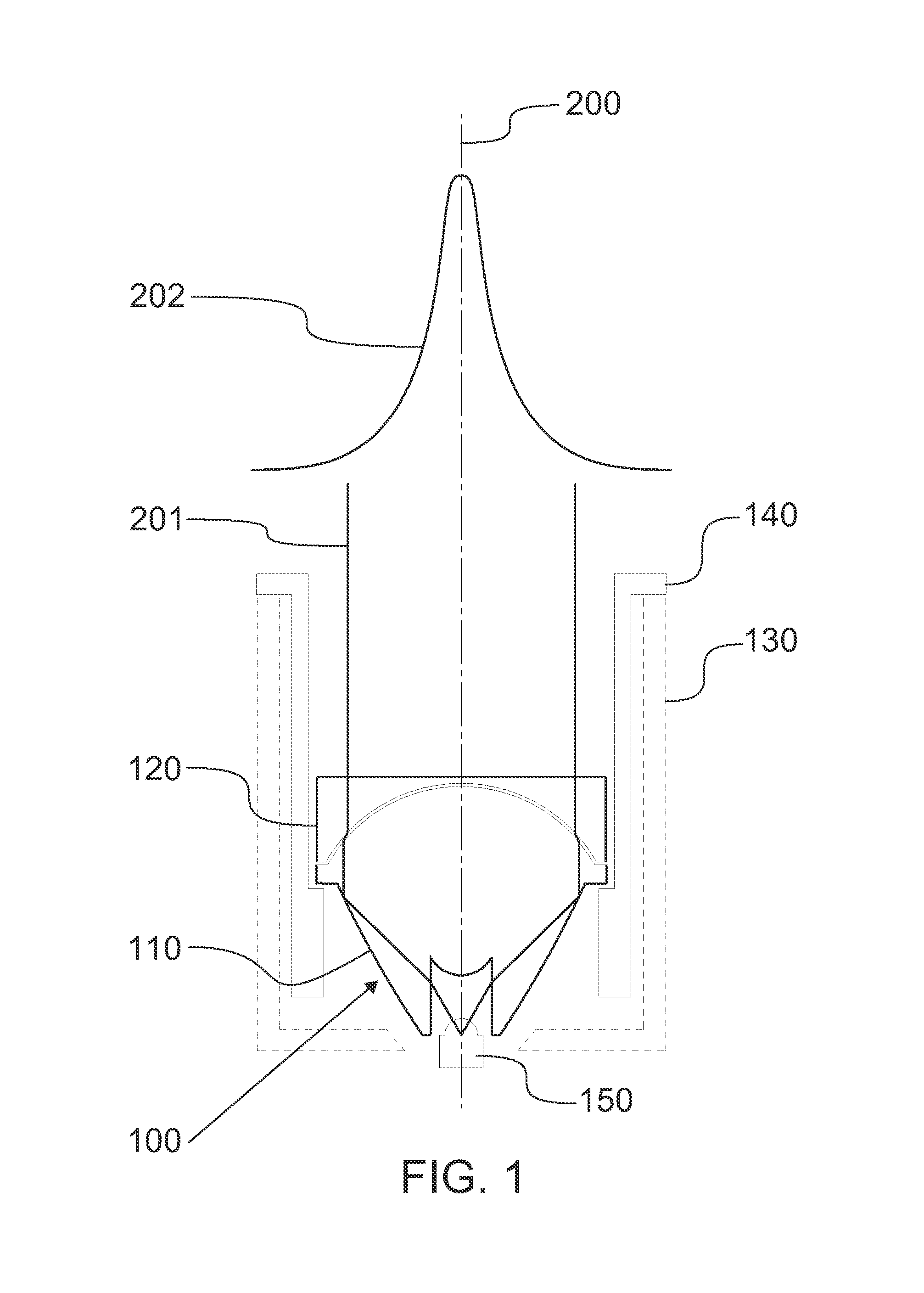
[0019]As can be seen from the embodiment of FIG. 1, a flush installed illuminator may be provided by arranging a novel lens arrangement 100 and a light source 150 into a frame 130 which is suitable for flush installation. The lens arrangement 100, which is shown in its minimum extended position in FIG. 1, includes a first lens 110, a second lens 120 and an adjustment mechanism 140 all arranged inside a frame 130. The combination of the frame 130, the lenses 110, 120 and the adjustment mechanism 140 form an illuminator housing which may be equipped with a light source 150. The frame 130 may be considered to include a first end, to which the light source 150 is fixed, and a second end opposing the first end for transmitting the light 201 of the light source 150 out of the illuminator housing. According to one embodiment, the light source 150 is an LED. The arrangement 100 has an optical axis 200 formed by the lenses 110, 120 to produce a light pattern 202. The formation of the optical...


PUM


Abstract

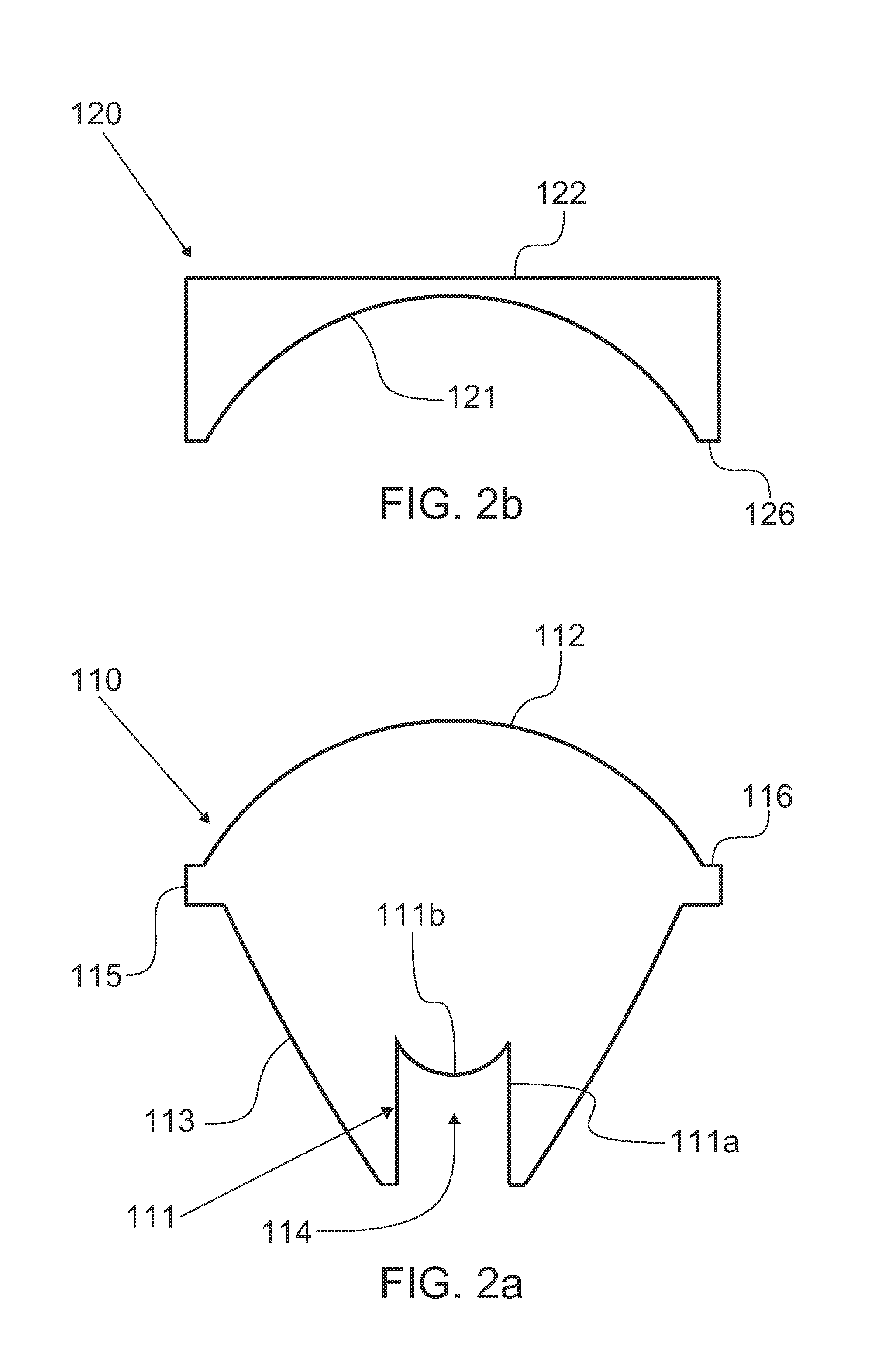
A novel lens arrangement features a first lens which is configured to be fixed to a light source and features an aspherical convex exit surface for transmitting light which received from the light source. A second lens is arranged to the optical axis of the first lens and features an aspherical concave entry surface which is arranged to receive light which transmitted by the first lens and which has substantially the same shape as that of the exit convex surface of the first lens. The first and second lens are configured to be moved along the optical axis in respect to each other between a minimum extended position, wherein the exit surface of the first lens is nested into the matching concave entry surface of the second lens, and maximum extended position, wherein second lens lies at the focal point of the first lens.

Description

FIELD OF THE INVENTION[0001]The present invention relates to lighting. In particular, the invention relates to a lens arrangement for an illuminator and to an illuminator housing for providing flush installed lighting.BACKGROUND ART[0002]Lighting is an important part of interior design. With ever rising awareness of energy consumption and significance of the quality of artificial light, producers and consumers alike have turned to LED's as an alternative in indoor lighting. LED's are known for their low power consumption and pleasant range of wavelength corresponding to that of natural light.[0003]There are a vast number of LED illuminators commercially available for indoor lighting. However, while there is ample supply of LED illuminators for consumers, there is scarce supply of LED illuminators for providing lighting for places of commerce, such as jewelry stores. Places of commerce typically set a particular set of boundaries for lighting solutions. In addition to economical and ...

Claims


Application Information

Patent Timeline
IPC IPC(8): F21V14/06
CPCF21V5/008F21V7/0091F21V7/05F21V7/07F21V14/06F21Y2115/10
Inventor LAUKKANEN, PETRI
Owner LEDIL
Learn More