Load driving apparatus related to light-emitting diode lamp and method thereof

a technology of light-emitting diodes and driving apparatuses, applied in the direction of electric variable regulation, process and machine control, instruments, etc., can solve the problems of increased power loss, increased cost, and increased cost of additional power loss, so as to maintain conversion efficiency, reduce additional cost, and avoid additional power loss

Active Publication Date: 2014-01-16
SPI ELECTRONICS
View PDF4 Cites 1 Cited by
  • Summary
  • Abstract
  • Description
  • Claims
  • Application Information

AI Technical Summary

Benefits of technology

[0029]According to the above descriptions, in the load driving apparatus adapted to the LED lamp and the method thereof, it is stopped conducting the generated DC operation voltage to the LED lamp when the lamp-off condition of the LED lamp is satisfied, and the generated DC operation voltage is conducted to the LED lamp when the lamp-on condition of the LED lamp is satisfied. Under either of the lamp-on condition and the lamp-off condition, the DC operation voltage of the LED lamp generated by the PWM-based power converter is not influenced. Therefore, the PWM controller is not malfunctioned or failed as the LED lamp is in a lamp-off state (due to that a working voltage supplied to the PWM controller is still higher than an under voltage lockout (UVLO) voltage of the PWM controller), so that the LED lamp is still capable of being turned on after it is turned off (as long as the lamp-on condition of the LED lamp is satisfied) without restarting the PWM controller.
[0030]On the other hand, since under either of the lamp-on condition and the lamp-off condition, the DC operation voltage of the LED lamp generated by the PWM-based power converter is not influenced. Therefore, an original power supply structure of the PWM-based power converter is unnecessary to be changed, so that additional power loss is avoided to maintain the conversion efficiency, and additional cost thereof is relatively low (compared to the method of the related art).
[0031]Moreover, even if under a design condition that the PWM controller does not have a latch over current protection (OCP) function, once the LED lamp is shorted, it is immediately and continuously stopped transmitting the generated DC operation voltage to the shorted LED lamp, i.e. a transmission path for supplying the generated DC operation voltage to the LED lamp is cut off. In this case, since the PWM-based power converter is not coupled to a load (i.e. non-load), the PWM controller is maintained to a non-load operation of low power consumption, so as to avoid unnecessary and repetitive large power loss until a new LED lamp is used for replacement.

Problems solved by technology

However, the conventional technical manner / solution for lamp-off probably causes malfunction or failure of a PWM controller in the driving device (due to that a working voltage supplied to the PWM controller is lower than an under voltage lockout (UVLO) voltage of the PWM controller), which results in a fact that the LED lamp cannot be again turned on after it is turned off unless the PWM controller in the driving device is restarted (for example, high voltage (HV) start).
In this way, not only additional power loss is produced to reduce conversion efficiency, additional cost thereof is also high.
On the other hand, under a design condition that the PWM controller does not have a latch over current protection (OCP) function, once the LED lamp is shorted, the PWM controller periodically / intermittently outputs a PWM signal with a very short duty cycle (since it is easy to reach an OCP point built in the PWM controller) to switch a power switch transistor in the driving device, which causes unnecessary and repetitive high power loss.

Method used


Image

  • Load driving apparatus related to light-emitting diode lamp and method thereof
  • Load driving apparatus related to light-emitting diode lamp and method thereof
  • Load driving apparatus related to light-emitting diode lamp and method thereof

Examples


Embodiment Construction

[0038]Reference will now be made in detail to the present preferred embodiments of the invention, examples of which are illustrated in the accompanying drawings. Wherever possible, the same reference numbers are used in the drawings and the description to refer to the same or like parts.

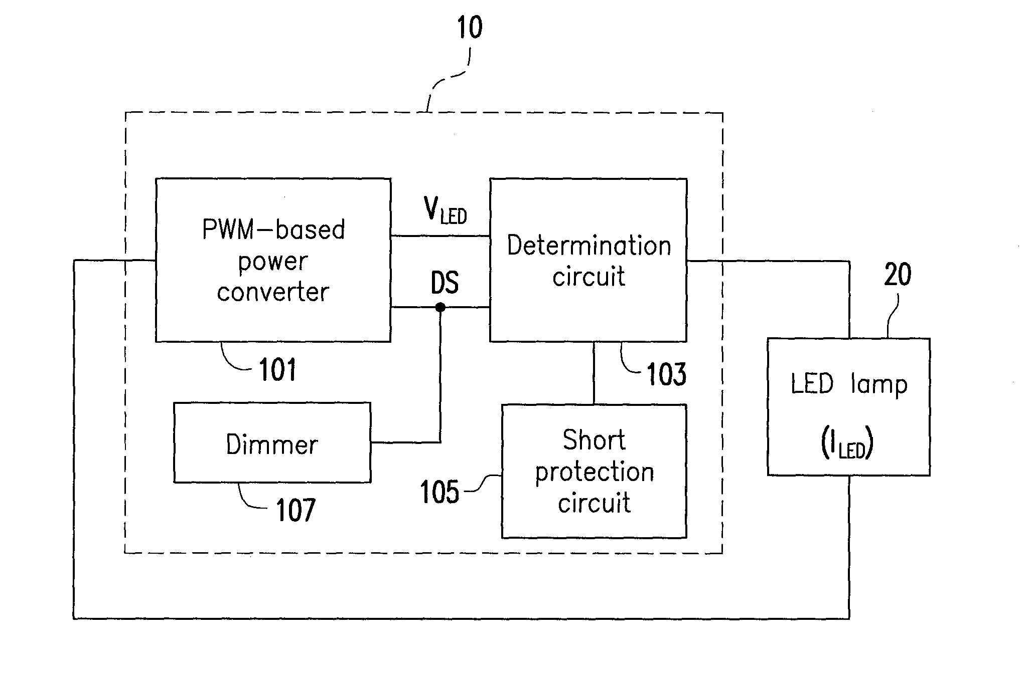
[0039]FIG. 1 is a schematic diagram of a load driving apparatus 10 adapted to a light-emitting diode (LED) lamp 20 according to an embodiment of the invention. Referring to FIG. 1, the load driving apparatus 10 includes a pulse width modulation (PWM)-based power converter 101, a determination circuit 103, a short protection circuit 105 and a dimmer 107.

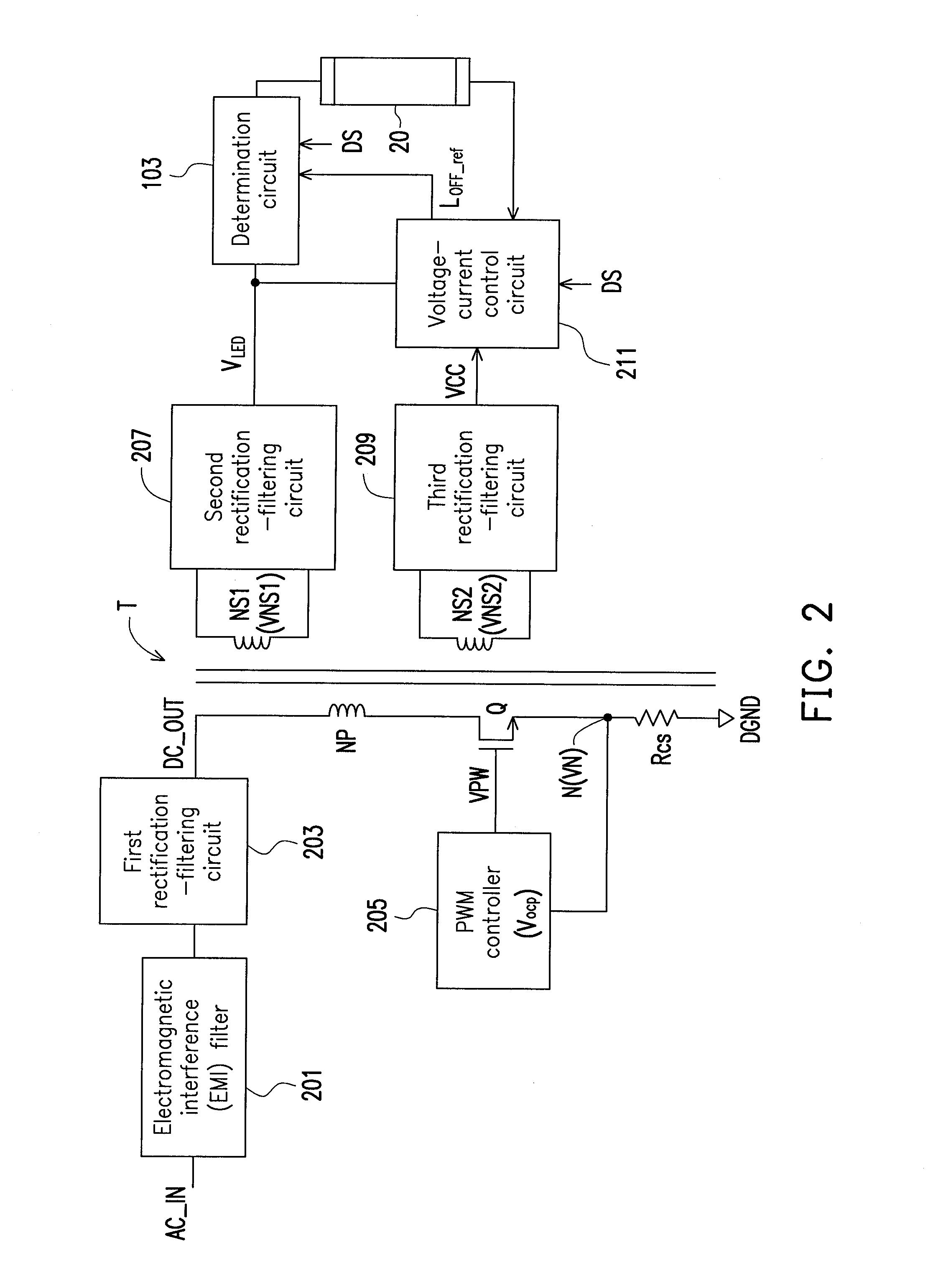
[0040]In the present embodiment, the PWM-based power converter 101 is coupled to the LED lamp 20, and a power conversion topology thereof can be a flyback power conversion topology, a forward power conversion topology, a boost power conversion topology, a buck power conversion topology, a boost-buck power conversion topology, or a push-pull power conve...


PUM


Abstract

A load driving apparatus related to an LED lamp and a method thereof are provided. The load driving apparatus includes a PWM-based power converter and a determination circuit. The PWM-based power converter is coupled to the LED lamp, and is configured to: generate a DC operation voltage of the LED lamp; and control a current flowing through the LED lamp in response to a dimming signal, so as to adjust a brightness of the LED lamp. The determination circuit is coupled to the PWM-based power converter and the LED lamp, and is configured to: receive the DC operation voltage; and stop conducting the DC operation voltage to the LED lamp in case that a lamp-off condition of the LED lamp is satisfied.

Description

CROSS-REFERENCE TO RELATED APPLICATION[0001]This application claims the priority benefit of china application serial no. 201210241192.6, filed on Jul. 12, 2012; the entirety of the above-mentioned patent application is hereby incorporated by reference herein and made a part of this specification.BACKGROUND[0002]1. Technical Field[0003]The invention relates to a load driving apparatus. Particularly, the invention relates to a load driving apparatus related to a light-emitting diode (LED) lamp and a method thereof.[0004]2. Related Art[0005]In the past two decades, engineers dedicated to develop new illumination light sources. The European Union specifically makes a “rainbow project”, and provides four conditions requiring the new illumination light source to satisfy, which are respectively high efficiency, energy saving, pollution-free, natural light simulation.[0006]Since a light-emitting diode (LED) has the above advantages, and is incomparable relative to a conventional illuminatio...

Claims


Application Information

Patent Timeline
Patent Type & Authority Applications(United States)
IPC IPC(8): H05B33/08H05B44/00
CPCH05B33/0809H05B33/089H05B33/0815Y02B20/347Y02B20/30H05B45/3725H05B45/382H05B47/25
Inventor YANG, CHENG-HUICHU, CHING-CHIA
Owner SPI ELECTRONICS
Why Eureka
Try Eureka