
Electrophoretic fluid

a technology of electrophoretic fluid and ectrophoretic fluid, applied in the field of electrophoretic fluid, can solve the problems of poor grey level bistability and vertical settling problems

Inactive Publication Date: 2014-01-09
E INK CALIFORNIA
View PDF2 Cites 140 Cited by
  • Summary
  • Abstract
  • Description
  • Claims
  • Application Information

AI Technical Summary

Benefits of technology

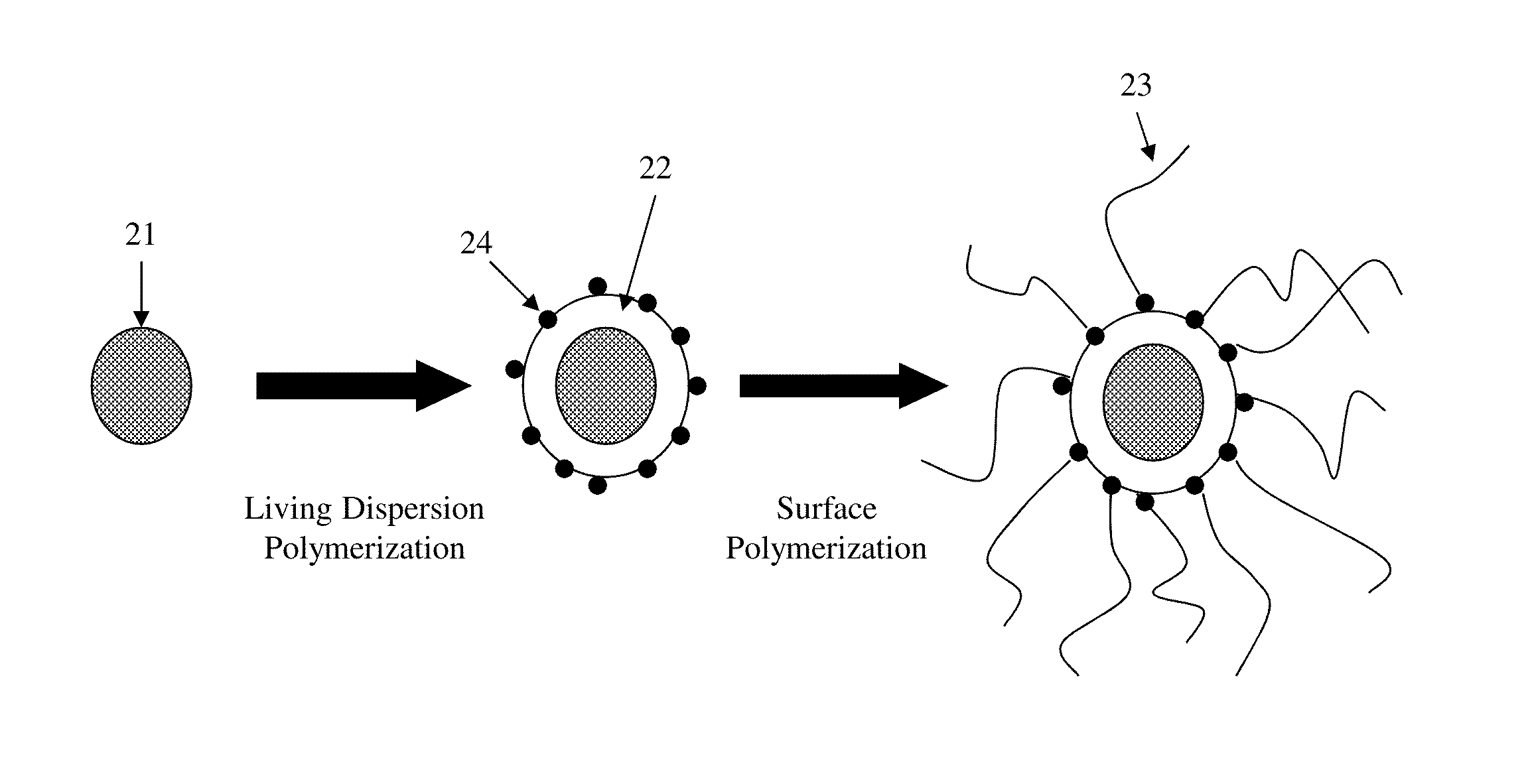
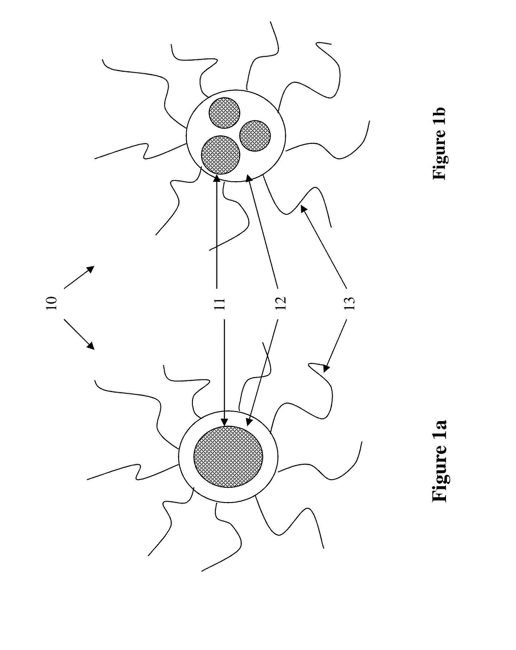
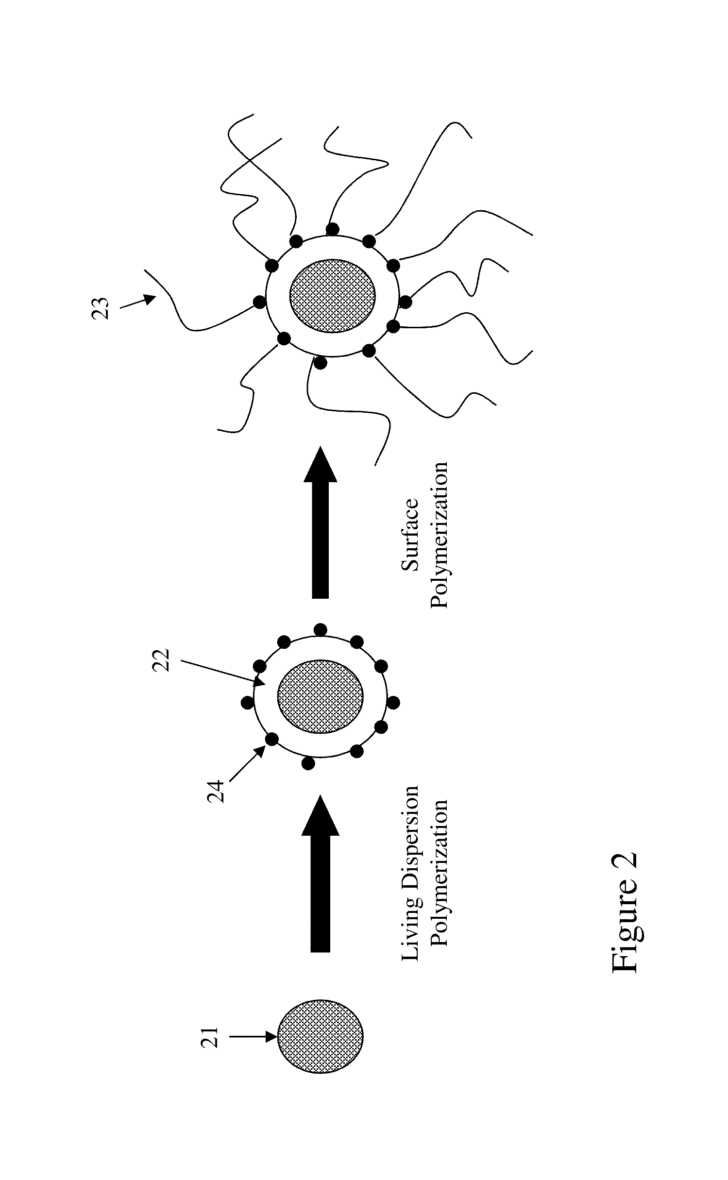
The present invention is about a new display fluid comprising charged composite pigment particles dispersed in a solvent. These particles have a core pigment particle, a shell coated over the core pigment particle, and steric stabilizer molecules on the surface of the composite pigment particles. The density of the composite pigment particles matches or is close to the density of the solvent. The difference between the density of the composite pigment particles and the solvent is less than 2 g / cm3. The composite pigment particles can have an inorganic or organic core particle, and the shell can be made from an organic material or a mixture of organic and other materials. The fluid can also contain other charged pigment particles of different colors. The invention also covers a method for tuning the charge level of a composite pigment particle by adding a co-monomer to the composition. The technical effects of this invention include improved properties of the display fluid for better image quality, reduced power consumption, and improved durability.

Problems solved by technology

Currently, the pigment particles in an electrophoretic fluid often have a density which is much higher than that of the solvent in which the particles are dispersed, thus causing performance issues, such as poor grey level bistability and vertical settling problems.

Method used


Image

  • Electrophoretic fluid
  • Electrophoretic fluid
  • Electrophoretic fluid

Examples


example 1

Step A: Deposition of Vinylbenzylaminoethylaminopropyl-trimethoxysilane on Black Pigment Particles

[0089]To a 1 L reactor, Black 444 (Shepherd, 40 g), isopropanol (320 g), DI water (12 g), ammonium hydroxide (28%, 0.4 g) and Z-6032 (Dow Corning, 16 g, 40% in methanol) were added. The reactor was heated to 65° C. with mechanical stirring in a sonication bath. After 5 hours, the mixture was centrifuged at 6000 rpm for 10 minutes. The solids were redispersed in isopropanol (300 g), centrifuged and dried at 50° C. under vacuum overnight to produce 38 g of desired pigment particles.

Step B: Preparation of Polymer Coating on Pigment Particles Through Dispersion Polymerization

[0090]Two (2) g of polyvinylpyrrolidone (PVP K30) was dissolved in a mixture of 94.5 g water and 5.5 g ethanol. The solution was purged with nitrogen for 20 minutes and heated to 65° C. The pigment particles (4 g) prepared from Step A was dispersed in a mixture of 3.0 g lauryl acrylate, 0.2 g divinylbezene and 0.03 g AI...

example 2

Synthesis of Colored Composite Pigment Particles

[0093]Hostaperm Red D3G 70-EDS (Clariant, 2.5 g), methyl methacrylate (8 g) and toluene (2 g) were added into a 20 ml vial and sonicated for 2 hours. To a 250 mL reactor, the above mixture, MCR-M22 (Gelest, 5.7 g) and DMS-T01 (Gelest, 30 g) were added. The reactor was heated to 70° C. with magnetic stirring and purged with nitrogen for 20 minutes, followed by the addition of lauroyl peroxide (0.07 g). After 19 hours, the mixture was centrifuged at 5000 rpm for 15 minutes. The solids produced were redispersed in hexane and centrifuged. This cycle was repeated twice and the solids were dried at room temperature under vacuum to produce the final particles. The polymer content of the particles produced was about 49% by weight, tested through TGA (thermal gravimetric analysis).


PUM

PropertyMeasurementUnit
Fractionaaaaaaaaaa
Fractionaaaaaaaaaa
Molar ratioaaaaaaaaaa

Abstract

The present invention is directed to a display fluid comprising charged composite pigment particles dispersed in a solvent. The composite pigment particle comprises at least a core pigment particle, a shell coated over the core pigment particle and steric stabilizer molecules on the surface of the composite pigment particle, wherein the shell is formed from a monomer and a co-monomer. A display fluid comprising the composite pigment particles provides improved display performance.

Description

[0001]This application is a continuation-in-part of U.S. application Ser. No. 13 / 549,028, filed Jul. 13, 2012; which is a continuation-in-part of U.S. application Ser. No. 13 / 363,741, filed Feb. 1, 2012; which claims priority to U.S. Provisional Application No. 61 / 439,302, filed Feb. 3, 2011; the contents of all applications referred to above are incorporated herein by reference in their entireties.FIELD OF THE INVENTION[0002]The present invention is directed to the preparation of composite pigment particles that can be used to form an electrophoretic fluid, and the resulting display fluid.BACKGROUND OF THE INVENTION[0003]An electrophoretic display (EPD) is a non-emissive device based on the electrophoresis phenomenon influencing charged pigment particles dispersed in a dielectric solvent. An EPD typically comprises a pair of spaced-apart plate-like electrodes. At least one of the electrode plates, typically on the viewing side, is transparent. An electrophoretic fluid composed of a...

Claims


Application Information

Patent Timeline
IPC IPC(8): C08L33/14C08L33/26G02F1/167
CPCC08L33/14C08L33/26G02F1/167G02F2001/1678
Inventor DU, HUILIN, CRAIGWANG, MINGZANG, HONGMEI
Owner E INK CALIFORNIA
Learn More