Optical information device, optical disc driving device, optical information recording device, optical information reproducing device, gap control method, and optical pickup
a technology of optical information and recording device, which is applied in the direction of digital signal error detection/correction, instruments, recording signal processing, etc., can solve the problems of deteriorating recording precision or reproduction precision, operating distance may vary, etc., and achieve high precision, stably record or reproduce information, the effect of high precision
- Summary
- Abstract
- Description
- Claims
- Application Information
AI Technical Summary
Benefits of technology
Problems solved by technology
Method used
Image

Examples
first embodiment
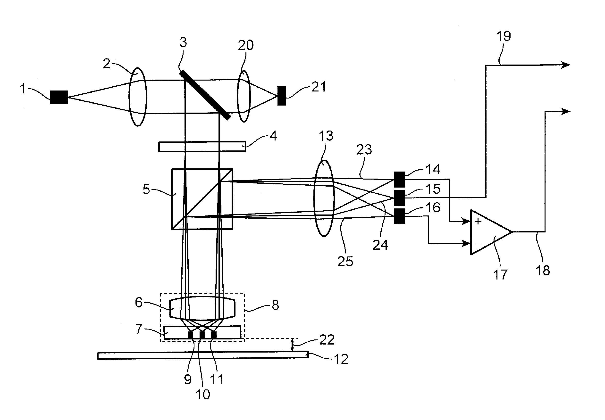
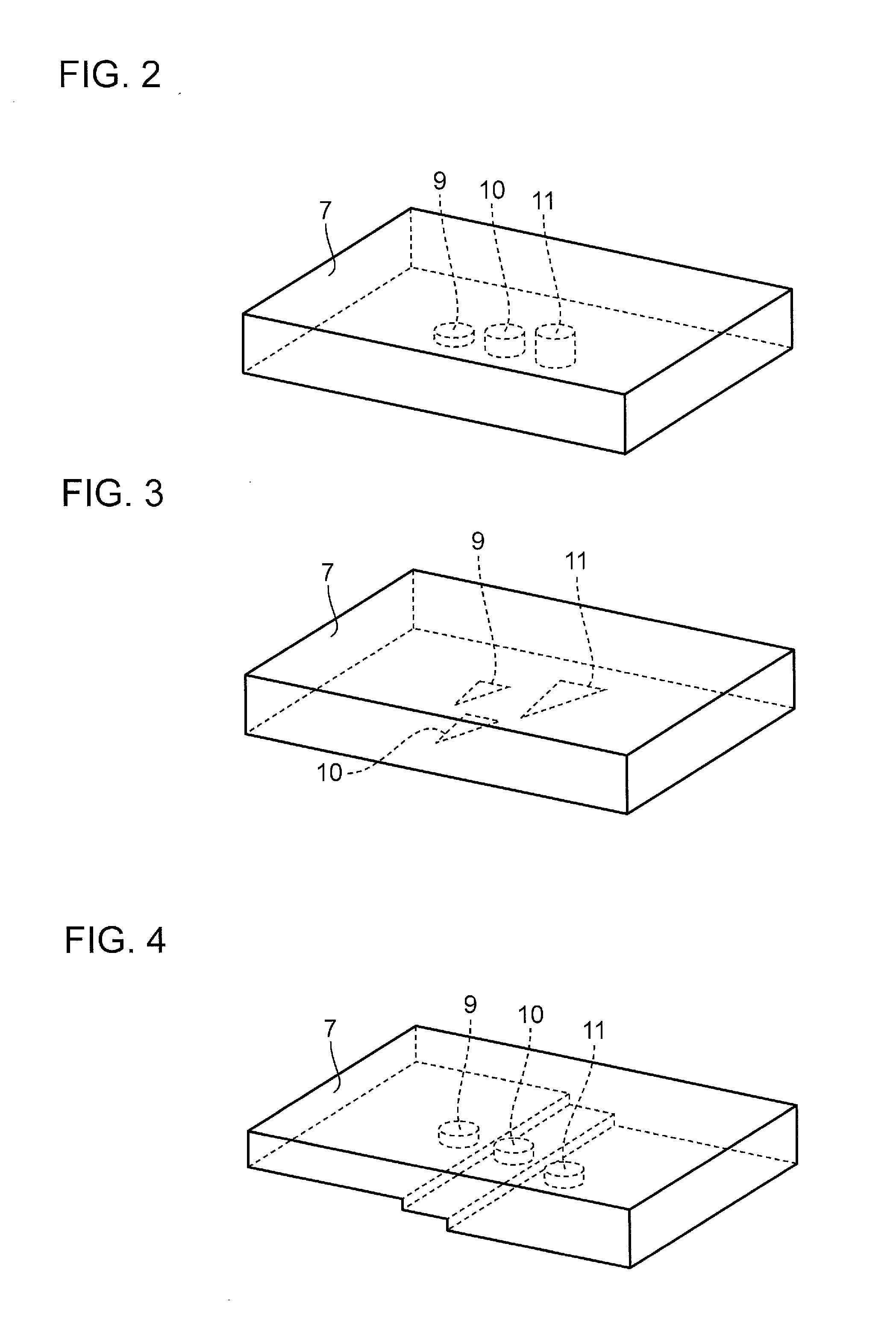
[0046]FIG. 1 is a diagram showing a configuration of an optical information device according to the first embodiment of the invention. The optical information device shown in FIG. 1 is provided with a laser light source 1, a collimator lens 2, a mirror 3, a diffraction element 4, a beam splitter 5, an objective lens unit 8, a detection lens 13, a first light detecting element 14, a second light detecting element 15, a third light detecting element 16, an arithmetic circuit 17, a light collecting lens 20, and a fourth light detecting element 21. The objective lens unit 8 is provided with an objective lens 6 and a substrate 7. The substrate 7 is provided with a first scattering medium 9, a second scattering medium 10, and a third scattering medium 11. It should be noted that an optical pickup is provided with the aforementioned configuration except for the arithmetic circuit 17.
[0047]Referring to FIG. 1, laser light emitted from the laser light source 1 is converted into parallel ligh...
second embodiment
[0112]FIG. 9 is a diagram showing a configuration of an optical information device according to the second embodiment of the invention. Constituent elements of the optical information device shown in FIG. 9 substantially the same or equivalent to those shown in FIG. 1 are indicated with the same reference numerals as those shown in FIG. 1, and description thereof is omitted herein.
[0113]Unlike the optical information device of the first embodiment shown in FIG. 1, the optical information device of the second embodiment shown in FIG. 9 is provided with a laser for recording or reproducing information, and another laser for detecting a gap interval.
[0114]Specifically, a first laser light source 1a is used for recording or reproducing information, and a second laser light source 1b is used for detecting a gap interval.
[0115]The optical information device shown in FIG. 9 is provided with the first laser light source 1a, the second laser light source 1b, a collimator lens 2, a mirror 3, ...
third embodiment
[0135]In this section, an optical disc driving device according to the third embodiment of the invention is described referring to FIG. 10.
[0136]FIG. 10 is a diagram showing a configuration of the optical disc driving device according to the third embodiment of the invention.
[0137]An optical information device 39 shown in FIG. 10 is the optical information devices described in the first embodiment and in the second embodiment. Constituent elements of the optical information device shown in FIG. 10 substantially the same or equivalent to those shown in FIG. 1 are indicated with the same reference numerals as those shown in FIG. 1, and detailed description thereof will be omitted herein.
[0138]As shown in FIG. 10, the optical disc driving device of the third embodiment is provided with an optical information device 39, a spindle motor 34, a signal processor 37, an interface 38, a servo controller 35, an unillustrated feed motor, and a system controller 36.
[0139]The spindle motor 34 is ...
PUM
| Property | Measurement | Unit |
|---|---|---|
| diameter | aaaaa | aaaaa |
| diameter | aaaaa | aaaaa |
| diameter | aaaaa | aaaaa |
Abstract
Description
Claims
Application Information
 - R&D
- Intellectual Property
- Life Sciences
- Materials
- Tech Scout
- Unparalleled Data Quality
- Higher Quality Content
- 60% Fewer Hallucinations
Browse by: Latest US Patents, China's latest patents, Technical Efficacy Thesaurus, Application Domain, Technology Topic, Popular Technical Reports.
© 2025 PatSnap. All rights reserved.Legal|Privacy policy|Modern Slavery Act Transparency Statement|Sitemap|About US| Contact US: help@patsnap.com