Illumination system with light source, radiation converting element and filter

a radiation conversion element and light source technology, applied in the field of illumination systems, can solve the problems of excluding them from practical use, long decay time and too weak absorption, and other approaches to reduce the bandwidth of emission spectra of wavelength converting elements, etc., and achieve the effect of reducing or eliminating

Active Publication Date: 2014-01-09
LUMILEDS
View PDF3 Cites 4 Cited by
  • Summary
  • Abstract
  • Description
  • Claims
  • Application Information

AI Technical Summary

Benefits of technology

[0004]It is an object of the present invention to mitigate or at least diminish the drawback of the known illumination system. More particularly, the invention aims at providing an illumination system with phosphor-based LEDs, which shows a narrow emission band in a certain area of the electromagnetic spectrum, and especially in the red part of the spectrum (appr. 600-630 nm).
[0008]An interesting embodiment of the illumination system according to the invention has the feature that the filter is an interference filter, which reflects blocked radiation back unto the radiation converting element. This measure improves the efficiency of the illumination system. When using an absorption filter, blocked radiation emitted either by the light source (primary radiation of substantially the whole emission spectrum) or by the radiation converting element (secondary radiation with wavelength shorter than the cut-off wavelength) is lost as heat due to its absorption in the filter. Using an interference filter has the advantage that the blocked primary and secondary radiation is reflected back unto the radiation converting element. Here the reflected radiation can be (re)absorbed, converted to radiation of a longer wavelength, and sent back to and through the interference filter. The part of the re-sent radiation having a wavelength longer than the cut-off wavelength of the interference filter can pass this filter. The (re)absorption and resending of the reflected radiation therefore results in a higher output efficiency of the illumination system.
[0011]A further interesting embodiment of the invented illumination system is characterized in that the absorption spectrum and the emission spectrum of the radiation converting element substantially overlap. It is noted that a ‘substantial overlap’ exists in case that the area of overlap is at least 5% of the total area covered by both the normalized emission spectrum and the normalized absorption spectrum. This measure can further enhance the efficiency of the invented system. This is due to the fact that the efficiency increase is resulting from re-absorption of emitted light reflected by the interference filter by the same phosphor material, followed by emission of this luminescent material. This process only occurs in case of spectral overlap. In this way, photon losses are minimized.
[0012]Another advantageous embodiment of the illumination system according to the invention is characterized in that the cut-off wavelength of the filter substantially coincides with the wavelength where the (normalized) absorption spectrum and the (normalized) emission spectrum of the radiation converting element cross. In practice this means that the cut-off wavelength differs less than 10 nm from the wavelength where the absorption spectrum and emission spectrum of the converting element cross. By selecting the cut-off wavelength according to this embodiment, an even further improvement of the light output efficiency can be obtained. This condition further optimizes the re-absorption of light with a relatively short wavelength and further reduces the band width of the resulting emission.

Problems solved by technology

It is noted that other approaches to reduce the bandwidth of the emission spectra of wavelength converting elements were not or only partially successful.
Line emitting phosphors with relatively narrow emission bands used in a first approach generally have too long decay times and too weak absorptions, which excludes them from practical use.
Moreover, many Eu2+-containing phosphors used in a second approach have rather broad emission bands or are unstable in (moist) air, which also limits their practical use.

Method used


Image

  • Illumination system with light source, radiation converting element and filter
  • Illumination system with light source, radiation converting element and filter
  • Illumination system with light source, radiation converting element and filter

Examples


Embodiment Construction

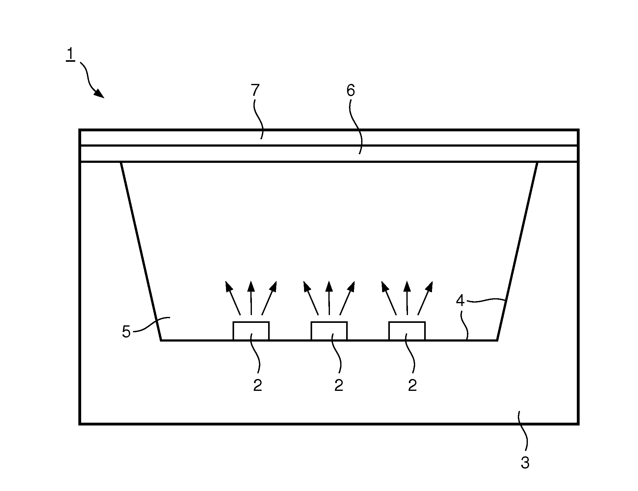
[0022]FIG. 1 illustrates in cross-section an embodiment of the illumination system 1 according to the present invention. Said system 1 comprises a number of light sources 2, which are embodied as a light emitting diodes (LEDs). Although different types of LEDs can be used, it is prefered to apply LEDs which are able to emit primary radiation having a wavelength of 550 nm or less. In the present device LEDs of the GaInN type are used, which are able to emit light having a wavelength maximum between 370-470 nm.

[0023]LEDs 2 are mounted on the bottom surface of a housing 3. On the inside walls of said housing 3, reflective means 4 have been provided, like a mirror of aluminum. During activation of the illumination system, an electrical voltage is applied via electrical leads on electrical connection portions of the LEDs. For reasons of simplicity, neither the electrical leads nor the electrical connection portions are shown. As a result of the activation, LEDs 2 emit radiation. This rad...


PUM


Abstract

The invention relates to an illumination system comprising 1) a light source arranged to emit primary radiation, 2) a radiation converting element arranged to convert at least part of the primary radiation into secondary radiation, and 3) a filter arranged to block radiation generated in the illumination system having a wavelength shorter than a certain cut-off wavelength. According to the invention, the filter is designed to block a part of the secondary radiation by having arranged the cut-off wavelength of the filter in the emission spectrum of the radiation converting element. Illumination devices according to this design show emission spectra with small bandwidth.

Description

FIELD OF THE INVENTION[0001]The invention relates to an illumination system comprising a light source arranged to emit primary radiation, a radiation converting element arranged to convert at least part of the primary radiation into secondary radiation and a filter arranged to block radiation generated in the illumination system having a wavelength shorter than a certain cut-off wavelength.BACKGROUND OF THE INVENTION[0002]An illumination system of the type described in the opening paragraph is known as such. More specifically, such a system is disclosed in the granted patent U.S. Pat. No. 7,402,840 B2. This document teaches an illumination system having a semiconductor light emitting device (LED), a wavelength converting material and a filter material. The light emitting device is able to emit a first light with a first peak wavelength, which is absorbed by the wavelength converting material. This material (most often a luminescent material, such as an inorganic phosphor) is able to...

Claims


Application Information

Patent Timeline
Patent Type & Authority Applications(United States)
IPC IPC(8): H01L33/50F21V9/40
CPCH01L33/50H01L33/44F21K9/64F21Y2115/10F21V9/40
Inventor RONDA, CORNELIS REINDERSHCHEKIN, OLEG BORISOVICH
Owner LUMILEDS
Why Eureka
Try Eureka