
Hay Storage System

a technology for storage systems and hay, which is applied in the field of hay storage systems, can solve the problems of reducing the nutrient, caloric and saleable value of baled crops, and reducing the environmental degradation of baled crops. , to achieve the effect of preventing undesired heat buildup or mold growth, and maximizing the curing of materials

Inactive Publication Date: 2014-01-09
BROWN JR OWEN JACKSON
View PDF19 Cites 13 Cited by
  • Summary
  • Abstract
  • Description
  • Claims
  • Application Information

AI Technical Summary

Benefits of technology

This invention is about a device and process for storing and drying large bales and bundles of grassy materials, such as straw and hay, to prevent mold and degradation. The device is a waterproof container that holds the materials and has a variable gas injection means and an adjustable vent to maintain air pressure inside. The gas flow is adjusted to maximize curing and prevent heat buildup and mold growth. The invention also includes a method of enhancing air movement through the bales by adding air-directing spacers and a plenum chamber between them. Additionally, a heating means can be added to speed up the drying process. Temperature and moisture sensors can be used to monitor and control the air flows and pressures to optimize curing and subsequent drying rates. Overall, this invention provides a low-cost, portable solution for storing, drying, and preserving large amounts of baled materials.

Problems solved by technology

One primary problem with baled fibrous materials is their propensity to rot, thermally decompose, burn, caramelize or develop mold if not properly dried, stored and preserved.
All these processes reduce the nutrient, caloric and saleable value of the baled crop.
All these methods still result in environmental degradation of the baled crops due to lack of adequate ventilation, moisture removal and bale temperature control.
This system is not cost effective to dry and subsequently store large volumes of ha bales, typically harvested by most farms.
The system requires inserting bales, drying the bales, then moving the bales to storage in order to make room for more bales to dry, adding to the labor costs for operation.
Also, the tight connection between the outer plastic sheet material and the outer surface of the bales can, without adequate heating means or prompt removal, lead to moisture condensation collecting between the two surfaces, leading to damaging mold growth on the outer surfaces of the bales.
The system requires the use of heated air, adding to the overall equipment and utility cost for operation.
The bidirectional means require the use of costly ducting and valves.
The system does not provide means to maximize curing of bales.
This method requires the use of costly chemicals that may have detrimental effects on the environment, and / or on the personnel applying them or on the animals subsequently ingesting the hay comingled with these chemical coatings.
Furthermore, the method does not disclose how to ensure every surface of each hay strand is to be coated, without substantial over-application and wastage of the coating materials.
Also, the method does nothing to address deleterious moisture levels deep within a typical hay bale, as the applications were only on 4″ thick test hales.
The time, labor and space required to coat bales and set them apart for drying prior to stacking would also substantially add to the cost of this method.
Such pressure can damage or destablize the resulting hay bale due to the disruption of the compacted hay, and leaves the damaged hay in the hole, effectively sealing off the rest of the hale from the drying effects of the hole.
This method results in wasted hay, in the form of cut ejected plugs.
It also does not address the problem of moisture from the environment entering the cut holes leading to rot from within.
It also has a negative impact of the structural integrity of the bales, preventing its use on large volumes of stacked hay bales typically harvested and stored by commercial farms.
It is also not easily adaptable to typical hay baling equipment, requiring the cutting / punching mechanisms to be periodically removed, sharpened and maintained.
This system requires an airtight film, that when in tight contact with the stack of bales results in pockets of trapped condensed moisture which will cause the outer bales to develop mold.
The bottom of the bales are in contact with the around and due moisture intrusion during rainy periods and due to no air circulation, this bottom section of the bales will develop mold and rot.
Because of the requirement to draw all the air through the stack of bales, this apparatus is not suitable for long stacks or large volumes of bales typically generated by typical commercial hay producers.
This apparatus and the abovementioned prior art does not address the critical heat cycle that each bale undergoes.
This and other similar methods of applying tightly adhering films do not address the moisture trapped within the center of the bales.
If used on fresh cut bales, the internal moisture migrates to the exterior round surfaces of the bales, where it subsequently condenses on the inside surface of the plastic sheet, particularly in the cool of the evenings, leading to mold growth on the outer surfaces of the bale.
These inventions also do not address the issue of controlling the bales heat cycle during critical curing and drying.
The predominate bacteria and yeast populations present on the standing crop, that are beneficial to curing the hay, are no longer viable as the moisture content drops below their range needed for sustenance.
If moisture content of baled hay is too high, then hay temperatures can rise into ranges that cause significant nutrient damage to the bale, kill the beneficial microbes, and even cause spontaneous combustion due to the accelerated exothermic chemical reactions.

Method used


Image

  • Hay Storage System
  • Hay Storage System
  • Hay Storage System

Examples


Embodiment Construction

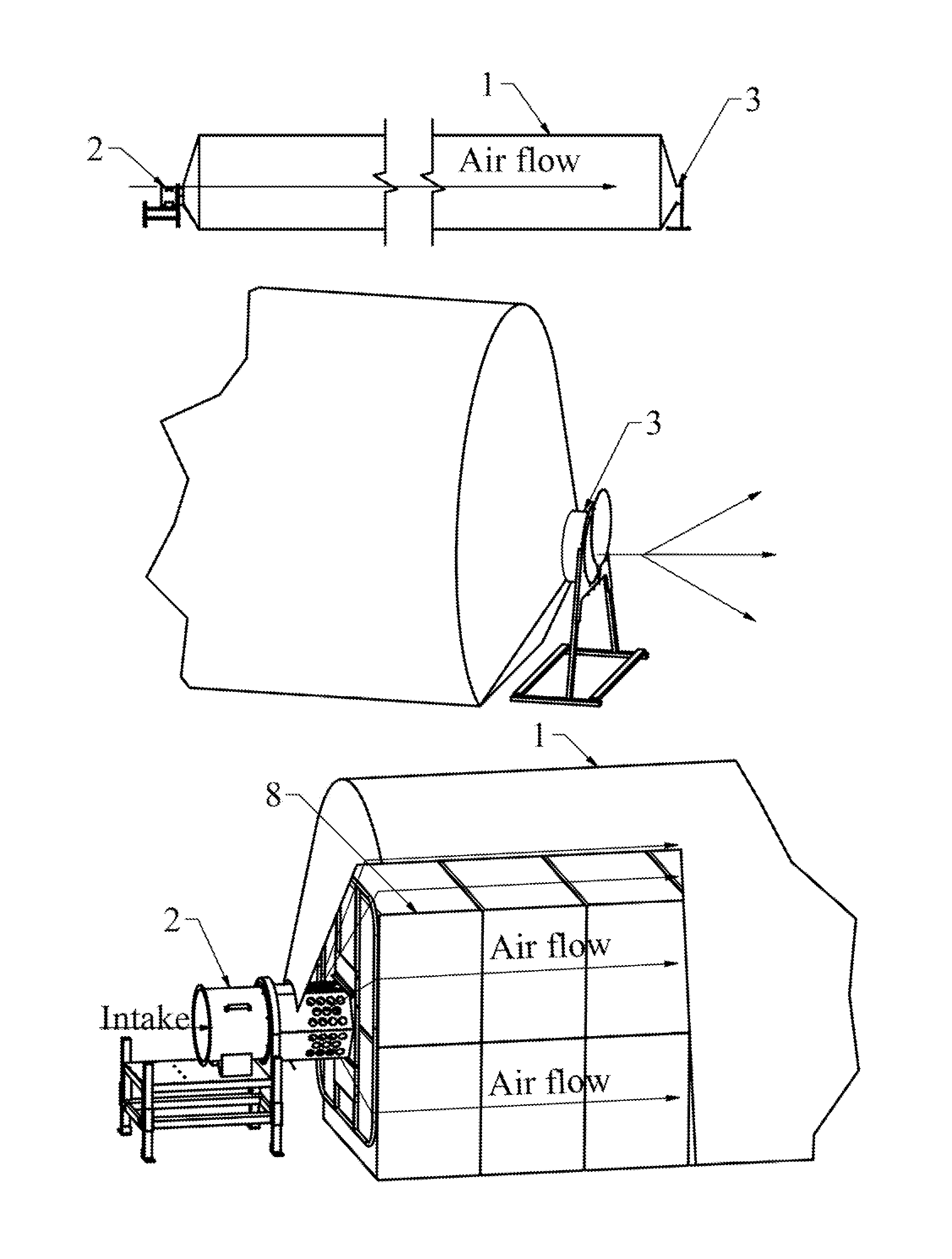
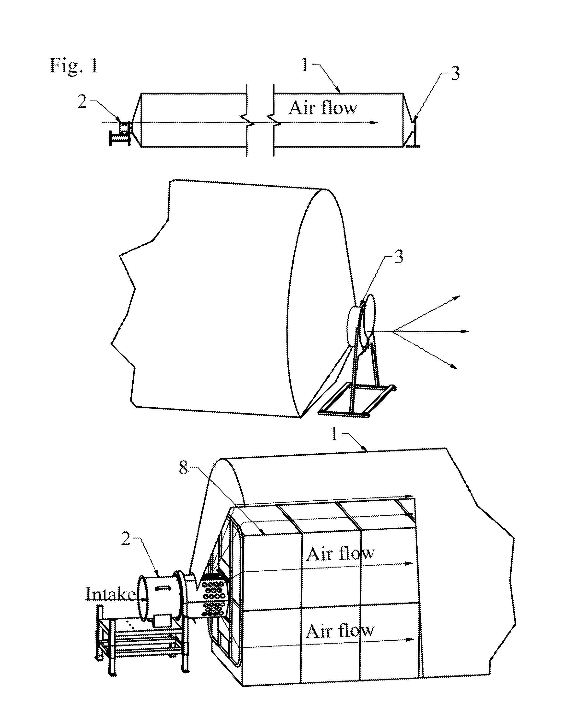
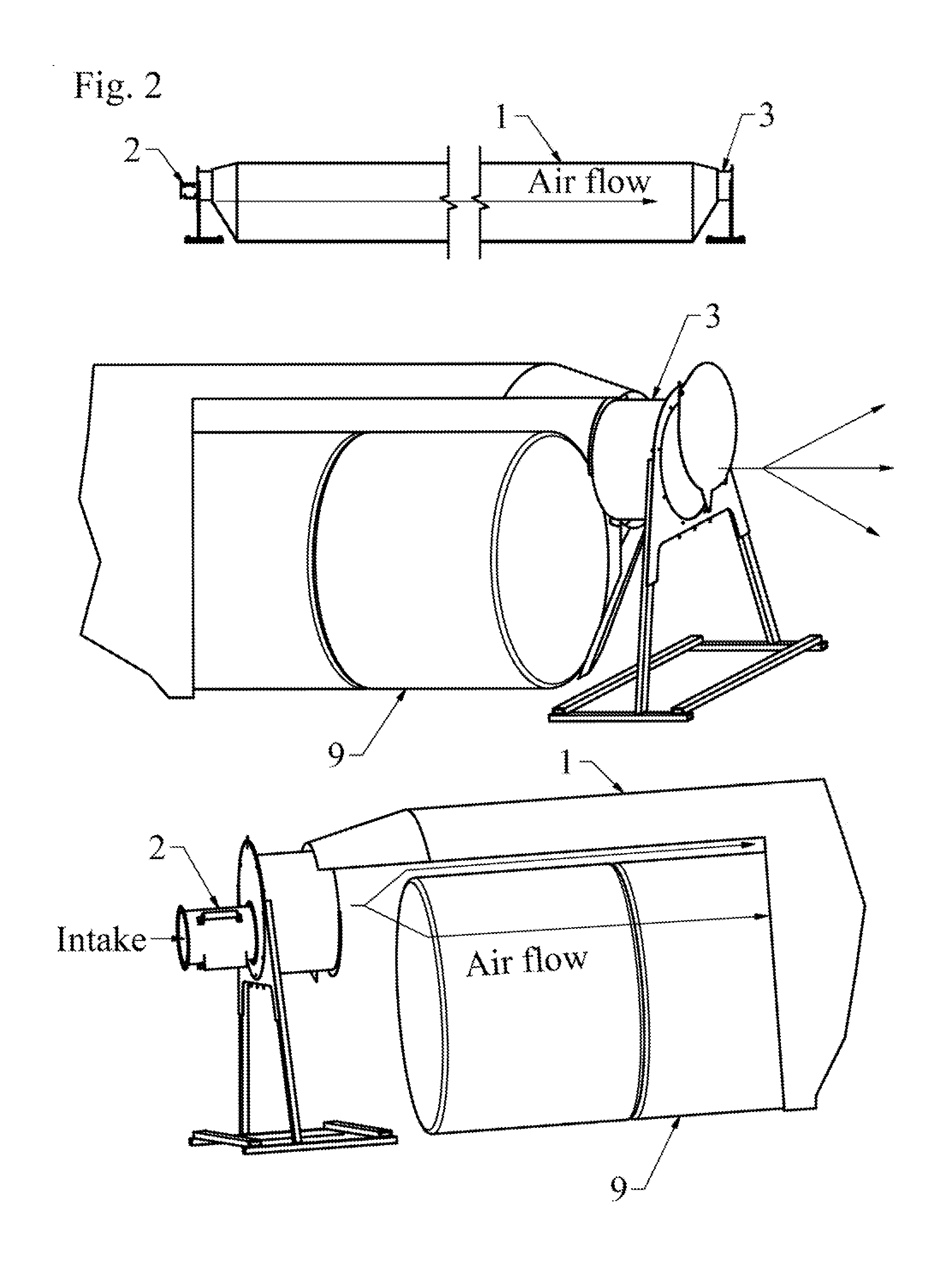
[0029]See FIG. 1. In one embodiment, a substantially waterproof container bag 1 typically fabricated from any group of extruded or cast plastic or water-resistant or coated paper or reinforced films, and of various different diameters dependent upon the size of bale or configuration, and cross section of bundles to be stored, is positioned in a generally horizontal position, typically rolled up to a substantially compact configuration, with total length of a few feet extending outward, however the bag may be totally or partially unrolled. The preferred method is to only unroll and extend sufficient length of bags to extend over the next hale or group of bundles in a single load. Finished unrolled lengths of these bags can vary from a few feet to up to several hundred feet long. This bag 1 is used to create a controlled environment for thy hay curing, drying and storage.

[0030]A fan, compressor, gas supply or other mechanical air injection means and support structure 2 is preferably s...


PUM


Abstract

A device and method for storing, curing, drying hay and other fibrous plant materials which includes a flexible water impermeable bag, as injection means at one end and an adjustable vent at the opposite end, and preferably spacer means between stacks of baled materials. The bales are progressively loaded at one end as the bag is unrolled and extended progressively laterally for additional bales. After loading, the gas injection and vent means are connected at ends of the bag and are adjusted to generate a back pressure within the bag to partially inflate it. The flowrate of gas or air is adjusted to maintain the temperature within the bales within an optimal range, preferably between ambient temperature and 120 degrees Fahrenheit enabling beneficial curing until sufficient moisture has been removed to prevent mold growth.

Description

CROSS REFERENCE TO RELATED APPLICATIONS[0001]This application claims the benefit of provisional patent application Ser. No. 61,669,422, filed 9 Jul., 2012.STATEMENT REGARDING FEDERALLY FUNDED RESEARCH [0002]Not applicableFIELD OF INVENTION[0003]The present invention relates to an apparatus and method for curing, drying and storing stacks of hay bales and other fibrous crops, such as grass, alfalfa, cotton and other fibrous materials which may be compressed and stacked in bales.BACKGROUND OF THE INVENTION[0004]Historically a typical agricultural process has been to cut forage, allow some degree of drying to occur, rake the fibrous material into windrows for further drying, then collect and store the forage at a desirable moisture content. Handling and storage of the cut forage was improved by baling. Early and current bales are typically square or rectangular, in the range of 20 to 100 pounds each. More modern bales are large units (from several hundred to a thousand pounds) of tight...

Claims


Application Information

Patent Timeline
Patent Type & Authority Applications(United States)
IPC IPC(8): A01F25/00A01F25/14
CPCA01F25/00A01F25/14A01F25/08A01F2025/142F26B9/006F26B2200/10Y02A40/58
Inventor BROWN, JR., OWEN JACKSON
Owner BROWN JR OWEN JACKSON
Learn More