
NFC Device with PLL Controlled Active Load Modulation

a technology of active load modulation and nfc device, which is applied in the field of near field communication (nfc), can solve the problems of poor magnetic coupling between small and large antennas, inhibiting the ability to pass energy from one antenna to the other, and compounding the problem of energy transfer

Active Publication Date: 2014-01-02
NXP USA INC
View PDF4 Cites 51 Cited by
  • Summary
  • Abstract
  • Description
  • Claims
  • Application Information

AI Technical Summary

Benefits of technology

The patent text describes a problem in the field of NFC devices, where poor magnetic coupling between small and large antennas can inhibit communication between devices. This can result in poor magnetic coupling even when the devices are close to each other, making it difficult to pass energy from one device to the other. The text proposes a solution using a phase-locked loop (PLL) to actively load modulate the antennas of the NFC devices, allowing them to communicate with each other even in the presence of poor magnetic coupling. The technical effect of this solution is to improve the magnetic coupling between the NFC devices and allow them to communicate with each other even in the absence of large antennas.

Problems solved by technology

The disparity in antenna size generally results in poor magnetic coupling between the small and large antennas, which inhibits the ability to pass energy from one antenna to the other.
This problem of energy transfer is compounded at low magnetic fields when the device with the small antenna is attempting to transmit using load modulation.
A large distance between the devices generally causes the received response signal to have a small voltage, and thus a poor magnetic coupling may result between the devices.
Several problems generally arise when NFC devices experience poor magnetic coupling.
For example, when only a small portion of energy transmitted from the first NFC device is actually received by the second NFC device, it becomes difficult for the second NFC device to be able to power itself from the magnetic field.
Further, poor magnetic coupling may inhibit the NFC devices' ability to perform load modulation because the second NFC device may only be able to effect a small portion of the total energy that was actually transmitted by the first NFC device.

Method used


Image

  • NFC Device with PLL Controlled Active Load Modulation
  • NFC Device with PLL Controlled Active Load Modulation
  • NFC Device with PLL Controlled Active Load Modulation

Examples


Embodiment Construction

[0017]The following Detailed Description refers to accompanying drawings to illustrate exemplary embodiments consistent with the disclosure. References in the Detailed Description to “one exemplary embodiment,”“an exemplary embodiment,”“an example exemplary embodiment,” etc., indicate that the exemplary embodiment described may include a particular feature, structure, or characteristic, but every exemplary embodiment may not necessarily include the particular feature, structure, or characteristic. Moreover, such phrases are not necessarily referring to the same exemplary embodiment. Further, when a particular feature, structure, or characteristic is described in connection with an exemplary embodiment, it is within the knowledge of those skilled in the relevant art(s) to affect such feature, structure, or characteristic in connection with other exemplary embodiments whether or not explicitly described.

[0018]The exemplary embodiments described herein are provided for illustrative pur...


PUM


Abstract

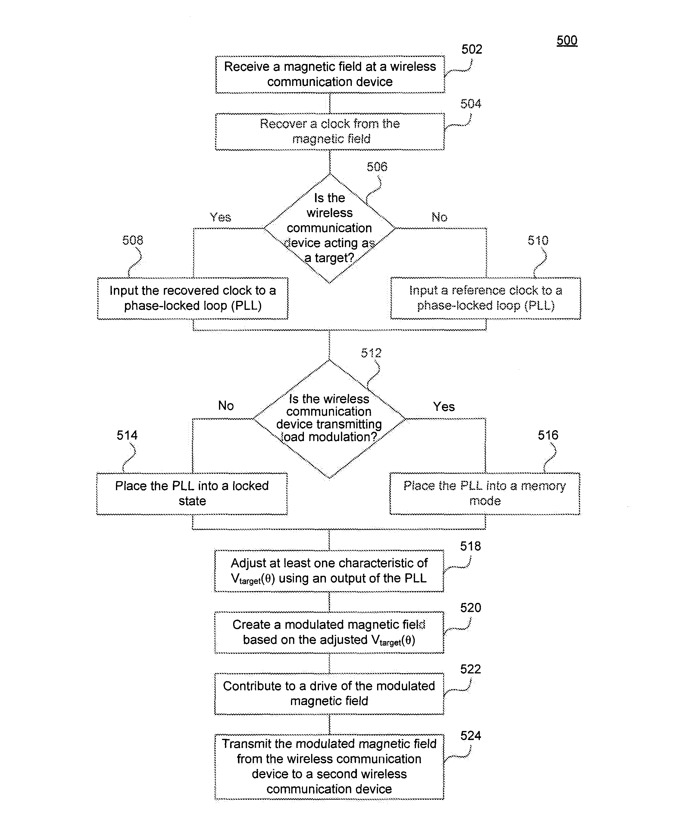
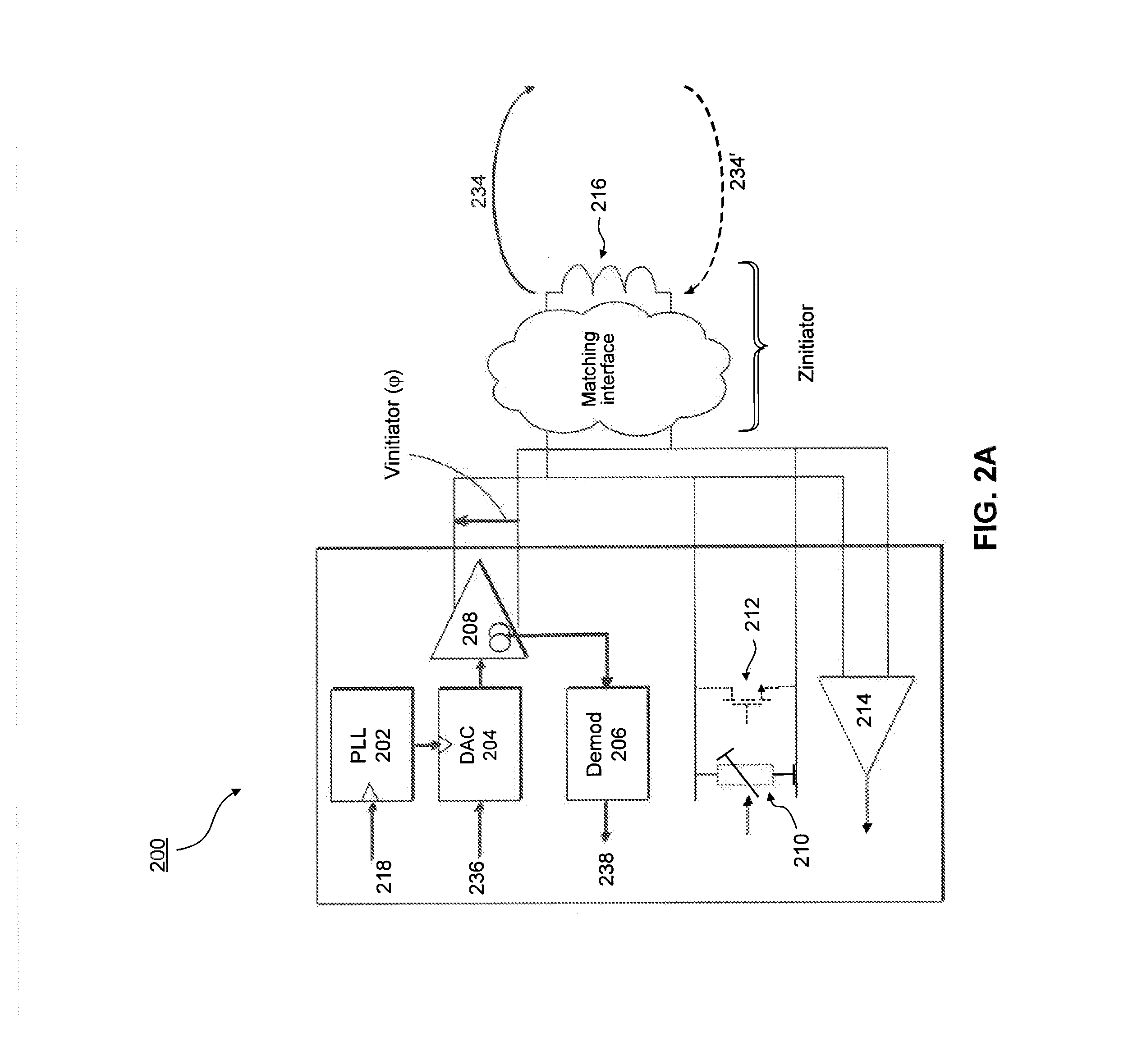
A wireless communication device for communicating in the near-field via active load modulation. The device including an antenna configured to receive a magnetic field, a recovery device configured to recover a clock from the magnetic field, and a multiplexer configured to receive the recovered clock and a reference clock, and to output one of the recovered clock and the reference clock based on a current operational state of the wireless communication device, The wireless communication device further including a shunt regulator configured to produce the active load modulation by modulating an impedance of the wireless communication device, a phase-locked loop (PLL) configured to receive one of the recovered clock and the reference clock and to utilize the received clock to control the active load modulation, and a driver configured to contribute to the active load modulation by adjusting an amplitude of a voltage across the antenna.

Description

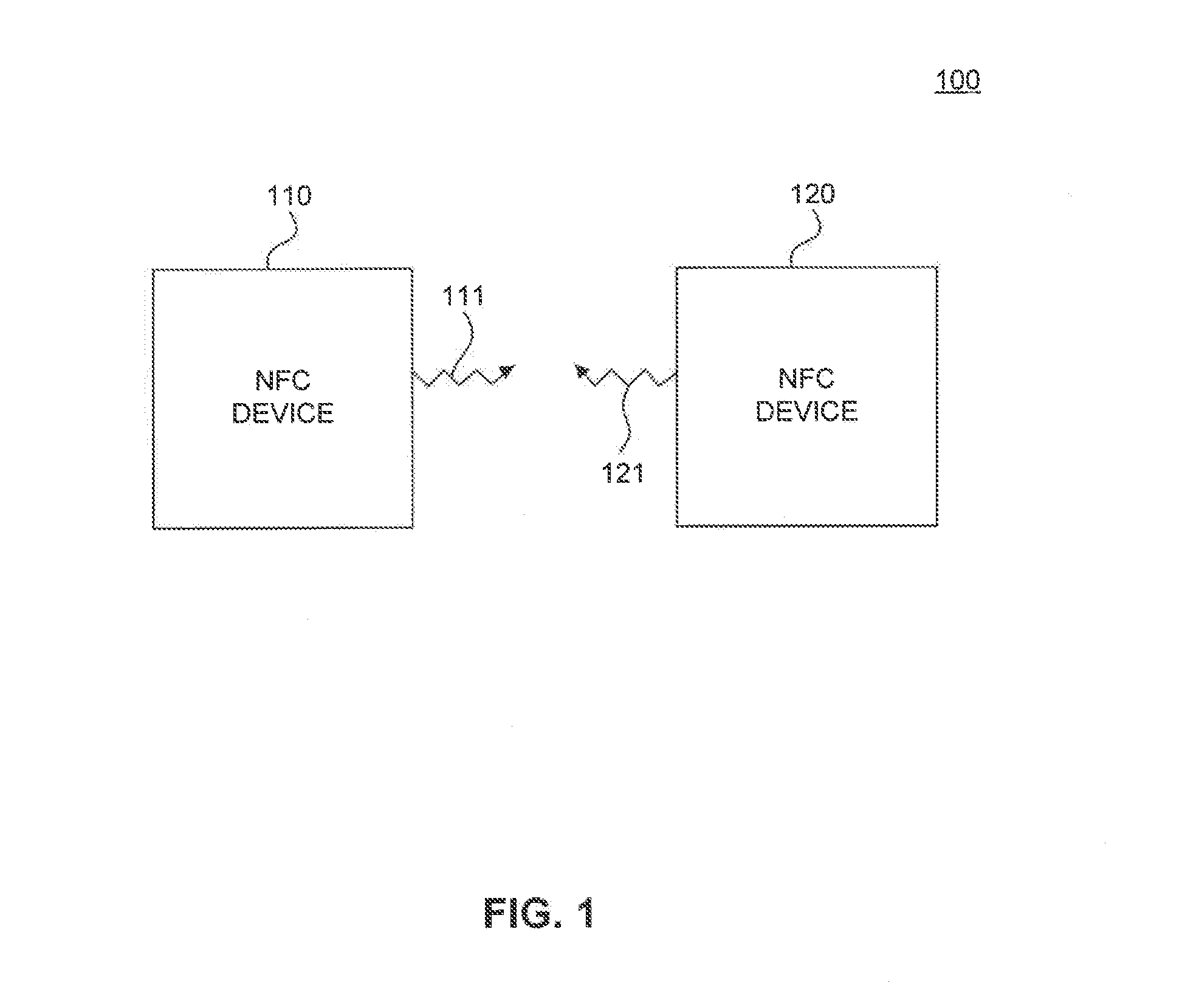
FIELD OF THE INVENTION[0001]The disclosure generally relates to near field communications (NFC), and more specifically to an NFC device for performing active load modulation controlled using a phase-locked loop (PLL).BACKGROUNDRelated Art[0002]Near field communication (NFC) devices are being integrated into communication devices, such as mobile devices to provide an example, to facilitate the use of these communication devices in conducting daily transactions. For example, instead of carrying numerous credit cards, the credit information provided by these credit cards could be stored onto an NFC device. The NFC device is simply tapped to a credit card terminal to relay the credit information to the terminal to complete a transaction. As another example, a ticket writing system, such as those used in a bus or train terminal, may simply write ticket fare information onto the NFC device instead of providing a ticket to a passenger. The passenger simply taps the NFC device to a reader t...

Claims


Application Information

Patent Timeline
Patent Type & Authority Applications(United States)
IPC IPC(8): H04L27/02H04B5/00H04L27/04
CPCG06K7/10237G06K19/0727H04B5/24H03L7/08H04B5/48
Inventor LEFLEY, ALASTAIR
Owner NXP USA INC
Learn More