Computer readable medium storing program for portable terminal, portable terminal, and method of data processing

a computer and portable terminal technology, applied in computing, digital output to print units, instruments, etc., can solve the problems of low operability and difficulty for users, and achieve the effect of easy image display

Inactive Publication Date: 2014-01-02
BROTHER KOGYO KK
View PDF3 Cites 8 Cited by
  • Summary
  • Abstract
  • Description
  • Claims
  • Application Information

AI Technical Summary

Benefits of technology

[0006]According to a technology related to the abovementioned portable terminal, it has become possible to check easily the image displayed on the image section and the image on the printed document, and therefore it is convenient. At the time of double-sided printing, it is necessary to select one of a short-edge binding and a long-edge binding. When the short-edge binding is selected, it is necessary to select one of short-edge out of two of short-edges, as a binding edge. When the long-edge binding is selected, it is necessary to select one of long-edge out of two of long-edges, as a binding edge. Because a printing method differs according to a binding position, it is necessary to select the binding edge. In detail, the printing method at the time of double-sided printing differs according to the binding edge, and whether the image to be printed is a landscape-oriented image or a portrait-oriented image. Here, the landscape-oriented image means an image which can be seen correctly when a short side of a print image 100 is extended in a direction away from the user, or in a vertical direction, and a long side of the print image 100 is extended in a left-right direction of the user, as shown in FIG. 3. Whereas, a portrait-oriented image or a vertically long image means an image which can be seen correctly when a long side of the print image 100 is extended in the direction away from the user, or in the vertical direction, and a short side of the print image 100 is extended in the left-right direction of the user. In a printing method in which a short-edge of the portrait-oriented image is set as the binding edge, an image of an odd-page is printed normally on a front surface of a printing paper and an image of an even-page is printed upside down on a rear surface of the printing paper. In a printing method in which a long-edge of the portrait-oriented image is set as the binding edge, an image of an odd-page is printed normally on a front surface of a printing paper and an image of an even-page is printed normally on a rear surface of the printing paper. In a printing method in which a short-edge of the landscape-oriented image is set as the binding edge, an image of an odd-page is printed normally on a front surface of a printing paper and an image of an even-page is printed normally on a rear surface of the printing paper. In a printing method in which a long-edge of the landscape-oriented image is set as the binding edge, an image of an odd-page is printed normally on a front surface of a printing paper and an image of an even-page is printed upside down on a rear surface of the printing paper. The printing method may differ according to a binding margin. In a printing method in which a short-edge of the printing paper is set as the binding edge, a margin at a side of the binding edge corresponding to one of two short-edges is wider than a margin at a side of the other of short-edge. In a printing method in which a long-edge of the printing paper is set as the binding edge, a margin at a side of the binding edge corresponding to one of two long-edges is wider than a margin at a side of the other of long-edge. Therefore, at the time of double-sided printing, a processing such as rotating image data of an image to be printed on the rear surface of the paper is necessary, and at the time of double-sided printing, it is necessary to select as to at which position out of the long-edge binding and the short-edge binding, to bind.

Problems solved by technology

In such selection method, it is difficult for a user to know intuitively as to which position of the image is to become the binding position, and therefore operability is low.

Method used


Image

  • Computer readable medium storing program for portable terminal, portable terminal, and method of data processing
  • Computer readable medium storing program for portable terminal, portable terminal, and method of data processing
  • Computer readable medium storing program for portable terminal, portable terminal, and method of data processing

Examples


second embodiment

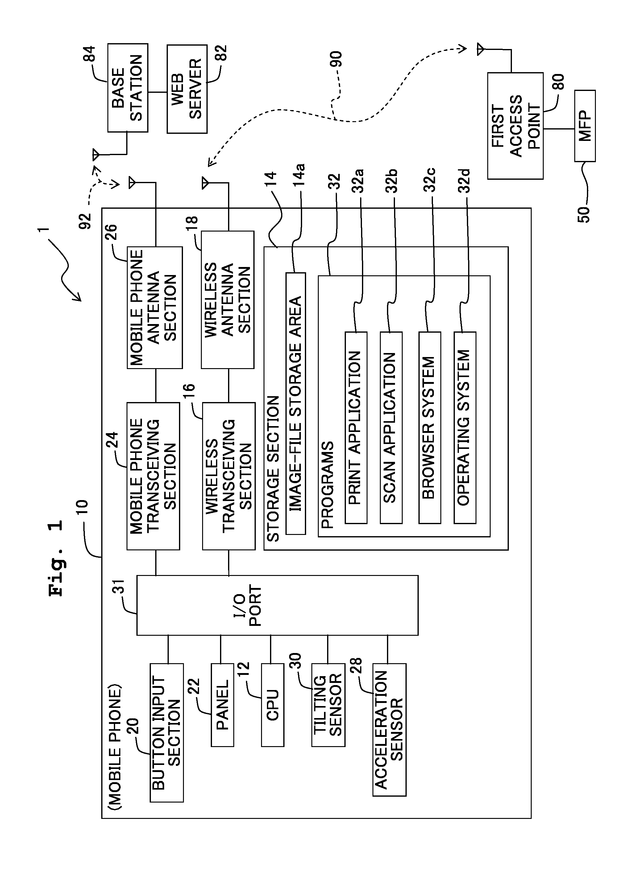
[0072]An operation of the mobile phone 10 according to a second embodiment will be described below. Since a configuration of the communication system 1 including the mobile phone 10 in the second embodiment is same as the configuration of the communication system 1 in the first embodiment, the description thereof will be omitted here.

[0073]In the mobile phone 10 according to the second embodiment, a plurality of documents set in the MFP 50 is scanned by using the scan application 32b, and a processing for setting a binding edge to image data of the scanned documents is executed. Concretely, a flow for setting the binding edge to the image data of the scanned documents will be described below by referring to FIGS. 9A and 9B.

[0074]At step S200, the CPU 12 transmits a command to execute a scan processing to the MFP 50. The MFP 50 scans the plurality of documents set on a feed tray in accordance with receiving the command, and generates plurality of image data. Moreover, the process adv...


PUM


Abstract

There is provided non-transitory computer readable medium including a program which is to be executed on a computer of a portable terminal including: a display section including four edges; and a sensor configured to output sensor data based on at least one of a proximity of an input medium to the display section, a contact of the input medium with the display section, and a posture of the portable terminal. The program causes the computer to execute displaying an image based on image data; setting a binding edge at the time of printing the image, based on the sensor data; and processing the image data based on the binding edge.

Description

CROSS REFERENCE TO RELATED APPLICATION[0001]The present invention claims priority from Japanese Patent Application No. 2012-146759, filed on Jun. 29, 2012, the disclosure of which is incorporated herein by reference in its entirety.BACKGROUND OF THE INVENTION[0002]1. Field of the Invention[0003]The present invention relates to a computer-readable medium storing a computer program which is readable by a computer of a portable terminal including a display section for displaying an image, a portable terminal, and a method for data processing.[0004]2. Description of the Related Art[0005]Size reduction and weight reduction of portable terminals have been progressing in recent years, and in many cases, portable terminals are used while being held in hands. In view of such situations, a portable terminal in which a top and a bottom of an image displayed on the display section coincide with a top and bottom in a direction of gravitational force, has been known. Furthermore, in the abovement...

Claims


Application Information

Patent Timeline
Patent Type & Authority Applications(United States)
IPC IPC(8): H04N1/00
CPCH04N1/00482H04N1/00228H04N1/00233H04N1/00466H04N2201/0094G06F3/1208G06F3/1256G06F3/1292
Inventor MIYATA, YUJI
Owner BROTHER KOGYO KK
Why Eureka
Try Eureka