
Duet power-driven window shade

a technology of window shades and power sources, applied in the field of windowshade, can solve the problems of reducing the operating effect, entanglement, inconvenience, etc., and achieve the effects of enhancing the rolling speed and the convenience of using, preventing entanglement, and increasing operating efficiency

Inactive Publication Date: 2014-01-02
BIN TERNG ENTERPRISE
View PDF6 Cites 7 Cited by
  • Summary
  • Abstract
  • Description
  • Claims
  • Application Information

AI Technical Summary

Benefits of technology

The present invention provides a duet power-driven window shade controlled by a unitary controlling device to enhance the rolling speed and the using convenience, preventing the entanglement, and increasing the operating efficiency. The duet power-driven window shade includes a frame, a driving device, a controlling device, and two covering sheets connected to the driving device. The controlling device receives an external controlling signal and has a processing unit and a memory unit with a preset value for analyzing and determining the controlling signal. The controlling signal is compared with the preset value and a driving signal is output accordingly to activate the covering sheets. The anti-reversing unit prevents interference of overloading currents or other factors, which allows the power source to receive the driving signal correctly. The invention ensures that the connecting members efficiently drive the operation for a smooth operation of the window shade.

Problems solved by technology

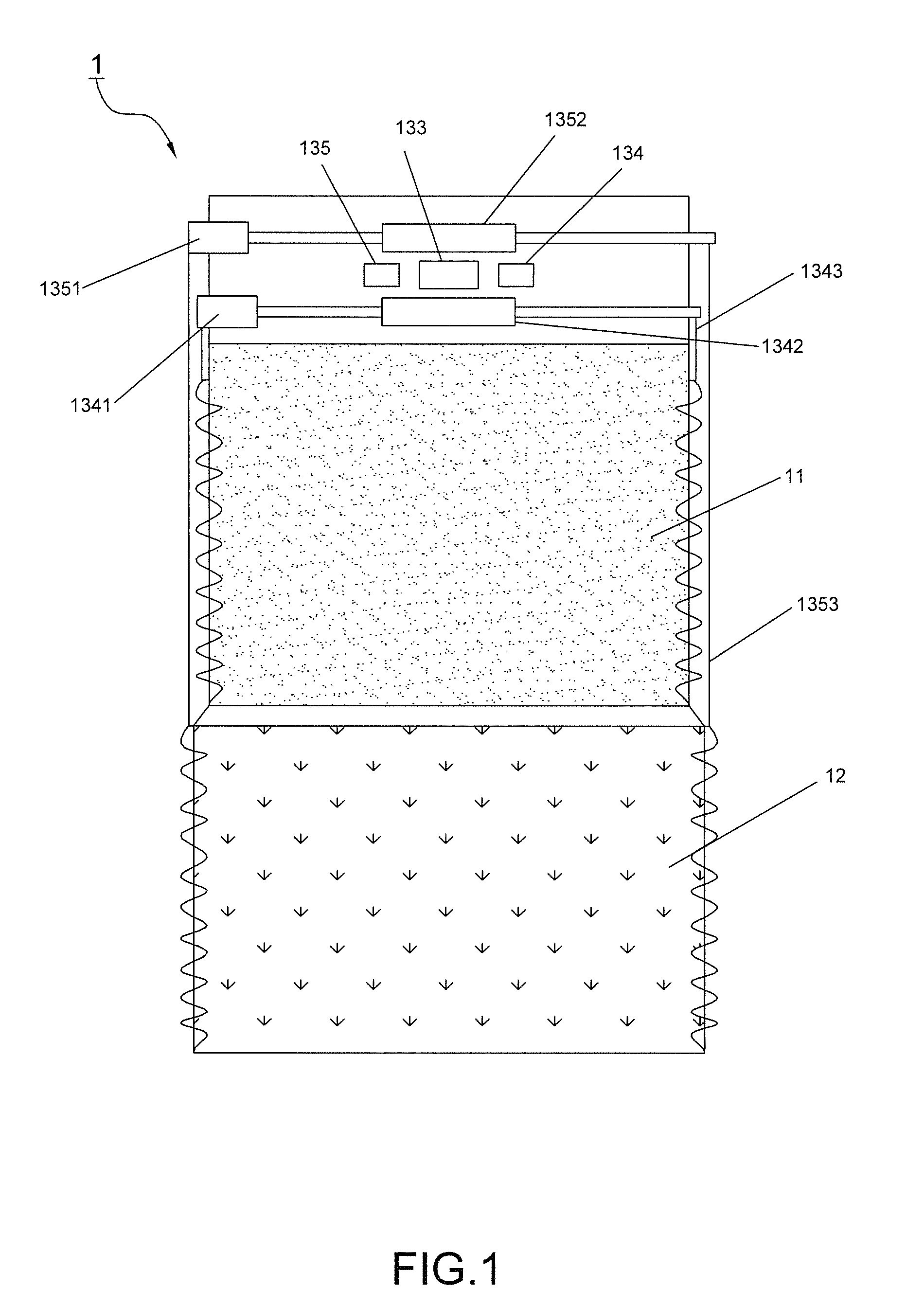
1. To control the rolling movement of the second covering sheet 12 before controlling the rolling movement of the first covering sheet 11, the rolling movement of the first covering sheet 11 does not act until the second covering sheet 12 completes its rolling action by pressing the button and the user further presses the button to activate the first covering sheet 11, which however consumes time and incurs inconvenience. Further, the first covering sheet 11 is subjected to the propelling motion of the second covering sheet 12 from downward to upward during the rolling action, with the result that the first rope 1343 gets loose when the first roller 1342 is not prepared to be rotated. In this manner, when the first covering sheet 11 is ready to be rolled up, the loose first rope 1343 may be entangled and cannot be convoluted smoothly. Thus, the disorderly first rope 1343 causes a malfunction and easily affects the following rolling and descending operations.
2. To control the rolling movement of the first covering sheet 11 up before controlling the rolling movement of the second covering sheet 12, the rolling movement of the first covering sheet 11 propels the second covering sheet 12 upward and causes the second rope 1353 of the second covering sheet 12 to become loose. Further, some impatient users may conduct a rolling movement of the second covering sheet 12 directly, while the first covering sheet 11 has not been completed rolled up. In view of the second covering sheet 12 subjected to the rolling movement of the first covering sheet 11, the second rope 1353 gets loose more easily and becomes failed to be convoluted round the second roller 1352 entirely. Thus, the disorderly second rope 1353 causes a malfunction and affects the following operation.
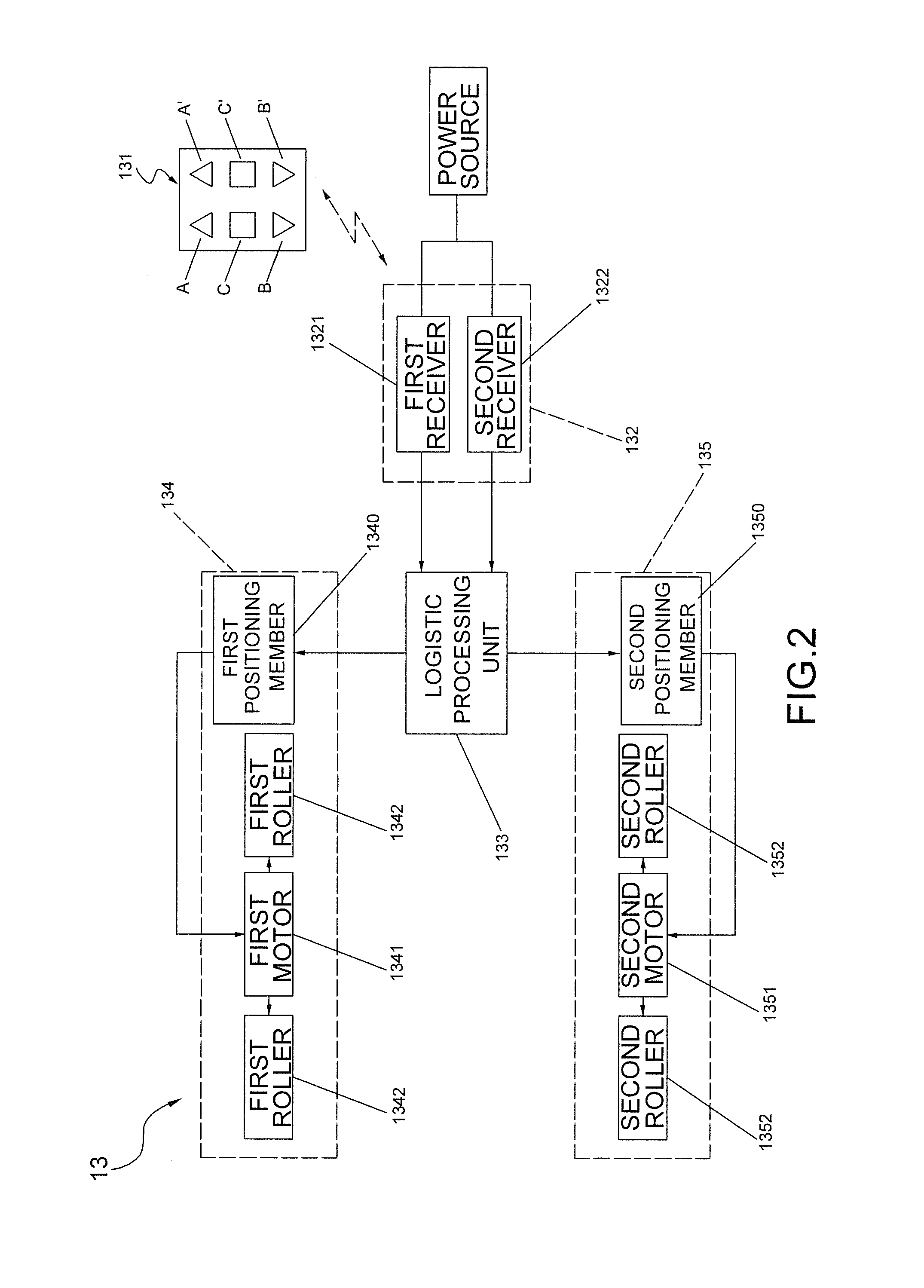
3. Since the remote control 131 is operated by controlling the covering sheets 11, 12 respectively, the user cannot press to activate the two controlling signals at the same time. This design causes the rolling movements of the first covering sheet 11 and the second covering sheet 12 unable to be operated concurrently and the separate first receiver 1321 and the second receiver 1322 unable to perform the concurrent receiving actions, which causes a time differential. As a result, the rotating speeds of the first roller 1342 and the second roller 1352 can not be identical owing to the time differential. Adversely, the ropes 1343, 1353 get loose easily, both of which also cannot be entirely convoluted round the rollers 1342, 1352 while completing the rolling movement of the covering sheets 11, 12. In the next time of rolling or descending actions, the disorderly ropes 1343, 1353 may malfunction and decrease the operating effect.

Method used


Image

  • Duet power-driven window shade
  • Duet power-driven window shade
  • Duet power-driven window shade

Examples


Embodiment Construction

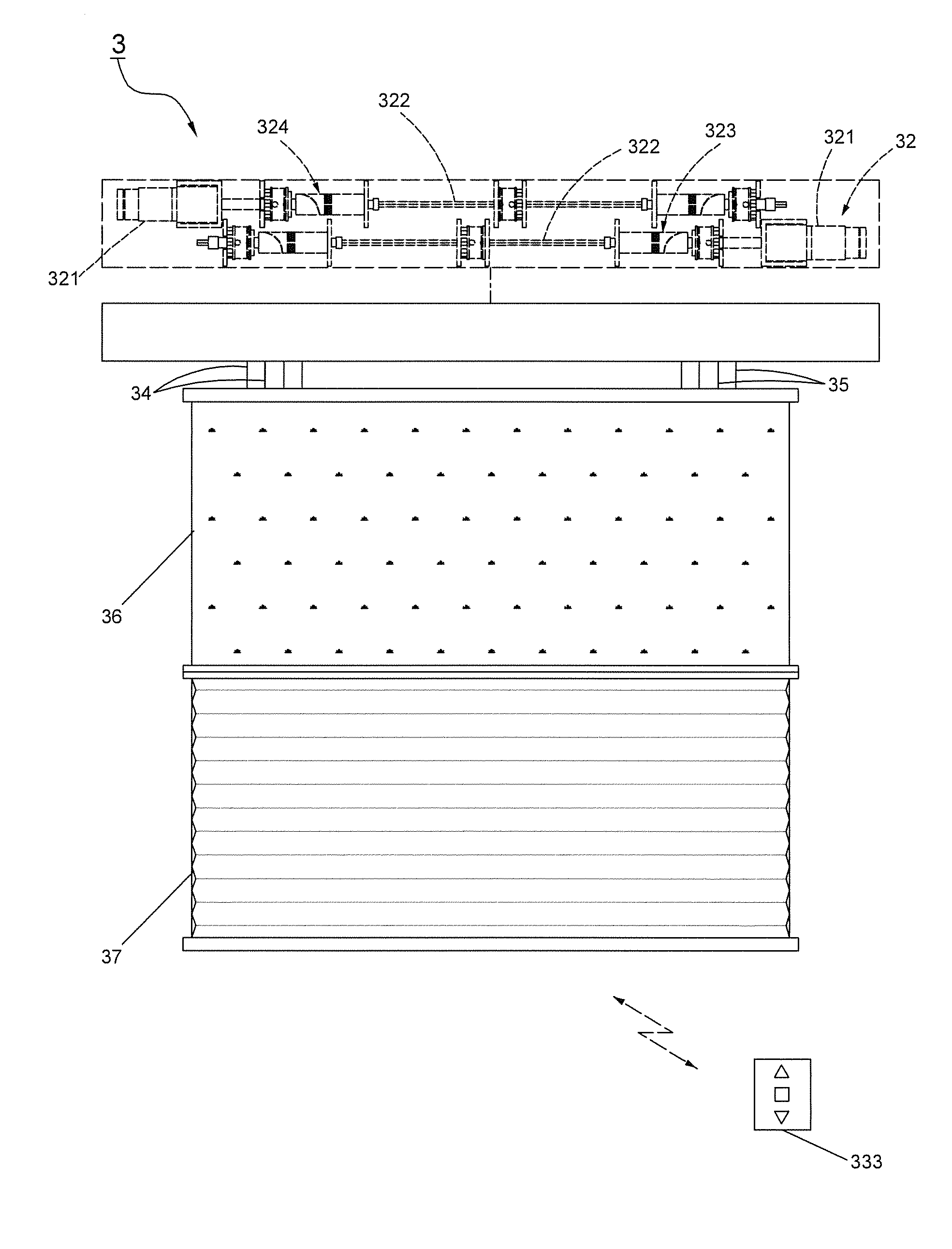
[0021]FIGS. 3 and 4 show a first preferred embodiment of a duet power-driven window shade 3 of the present invention. The duet power-driven window shade 3 comprises a frame 31, a driving device 32 disposed in the frame 31, a controlling device 33 connected to the driving device 32, a first connecting member 34 as well as a second connecting member 35 activated by the driving device 32, a first covering sheet 36 connected to the first connecting member 34, and a second covering sheet 37 connected to the second connecting member 35. Wherein, the driving device 32 includes at least one power source 321, a shaft 322 triggered by the power source 321, a first roller 323 connected to the first connecting member 34 and driven by the power source 321, and a second roller 324 connected to the second connecting member 35 and driven by the power source 321. In this embodiment, two power sources 321 are adopted as illustrated. A bottom end of the first covering sheet 36 is connected to the seco...


PUM


Abstract

A duet power-driven window shade comprises a controlling device to receive an external controlling signal, which is then analyzed, determined and compared with a preset value in a memory unit of the controlling device. A driving signal is output via a processing unit according to a comparing result. A power source thence brings convolutions of a first covering sheet and a second covering sheet in sequence or concurrently for increasing the rolling speed and the using convenience and allowing the connecting members connected to the covering sheets to be efficiently rolled up without entanglement so that the duet power-driven window shade is smoothly operated.

Description

BACKGROUND OF THE INVENTION[0001]1. Field of the Invention[0002]The present invention relates to a window shade, particular to a duet power-driven window shade.[0003]2. Description of the Related Art[0004]Referring to FIGS. 1 and 2, a conventional shade 1 of a TW patent publication No. M414904 includes a first covering sheet 11, a second covering sheet 12 connected to a bottom end of the first covering sheet 11, and a controlling device 13. Wherein the controlling device 13 includes a remote control 131 emitting an external controlling signal, at least one receiver 132 receiving the controlling signal, a logistic processing unit 133 electrically connected to the receiver 132, a first controlling module 134 electrically connected to the logistic processing unit 133, and a second controlling module 135 electrically connected to the logistic processing unit 133. The receiver 132 includes a first receiver 1321 and a second receiver 1322. The first controlling module 134 has a first posi...

Claims


Application Information

Patent Timeline
Patent Type & Authority Applications(United States)
IPC IPC(8): A47H5/032
CPCA47H5/0325E06B9/262E06B9/322E06B2009/2441E06B9/74
Inventor YEH, WEI-CHENG
Owner BIN TERNG ENTERPRISE
Learn More