Vascular occlusion device

a vascular occlusion and device technology, applied in the field of vascular occlusion devices, can solve the problems of restricting compressibility and loss of device flexibility, and achieve the effect of improving vascular occlusion

Inactive Publication Date: 2013-12-19
COOK MEDICAL TECH LLC
View PDF17 Cites 5 Cited by
  • Summary
  • Abstract
  • Description
  • Claims
  • Application Information

AI Technical Summary

Benefits of technology

[0009]The frame has a configurable structure able to provide occlusion by a simple mechanical movement of the end members, in which occlusion occurs by means of the fibrous barrier. The structure moreover enables the use of a frame made of fine material which is able to be compressed radially to a relatively small diameter, less than is possible with prior art structures. The fibrous barrier member provides similar advantages.
[0012]The biasing member ensures deployment of the device, that is its radial expansion, allowing the use of a frame which is not necessarily able to impart an adequate deployment force per se. This also adds to the ability to minimise the structure and thus volume of the frame and to minimise the radially contracted footprint of the device for deployment. It can also lead to a highly configurable frame able to adapt to the shape and contour of the vessel in which it is deployed.
[0013]In the preferred embodiment, the frame is generally cylindrical in at least one configuration thereof. A cylindrical occlusion device can ensure reliable positioning in a vessel.

Problems solved by technology

These features can lead to restrictions in compressibility as well as loss of flexibility of the device, particularly when compressed for delivery.

Method used


Image

  • Vascular occlusion device
  • Vascular occlusion device
  • Vascular occlusion device

Examples


Embodiment Construction

[0034]It is to be understood that the drawings are schematic only and are not to scale. They are of a form which is intended to facilitate the understanding of the teachings herein.

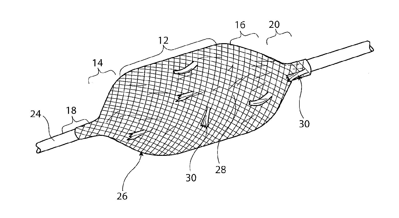
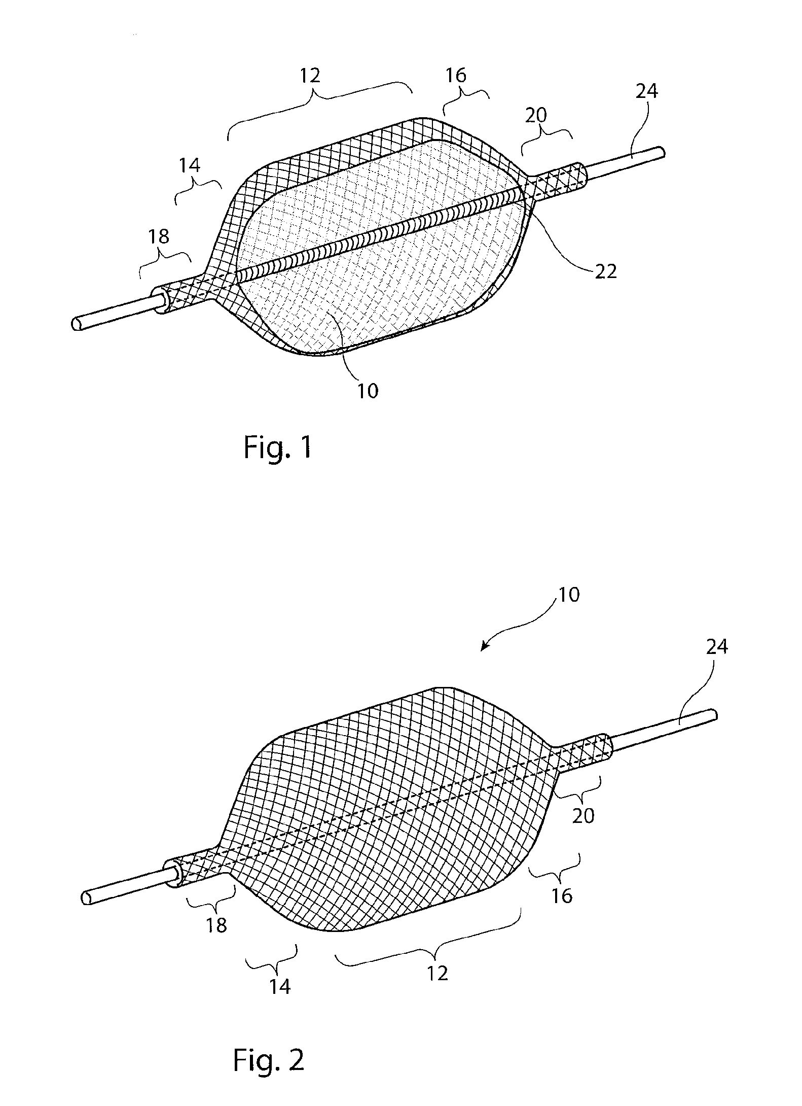
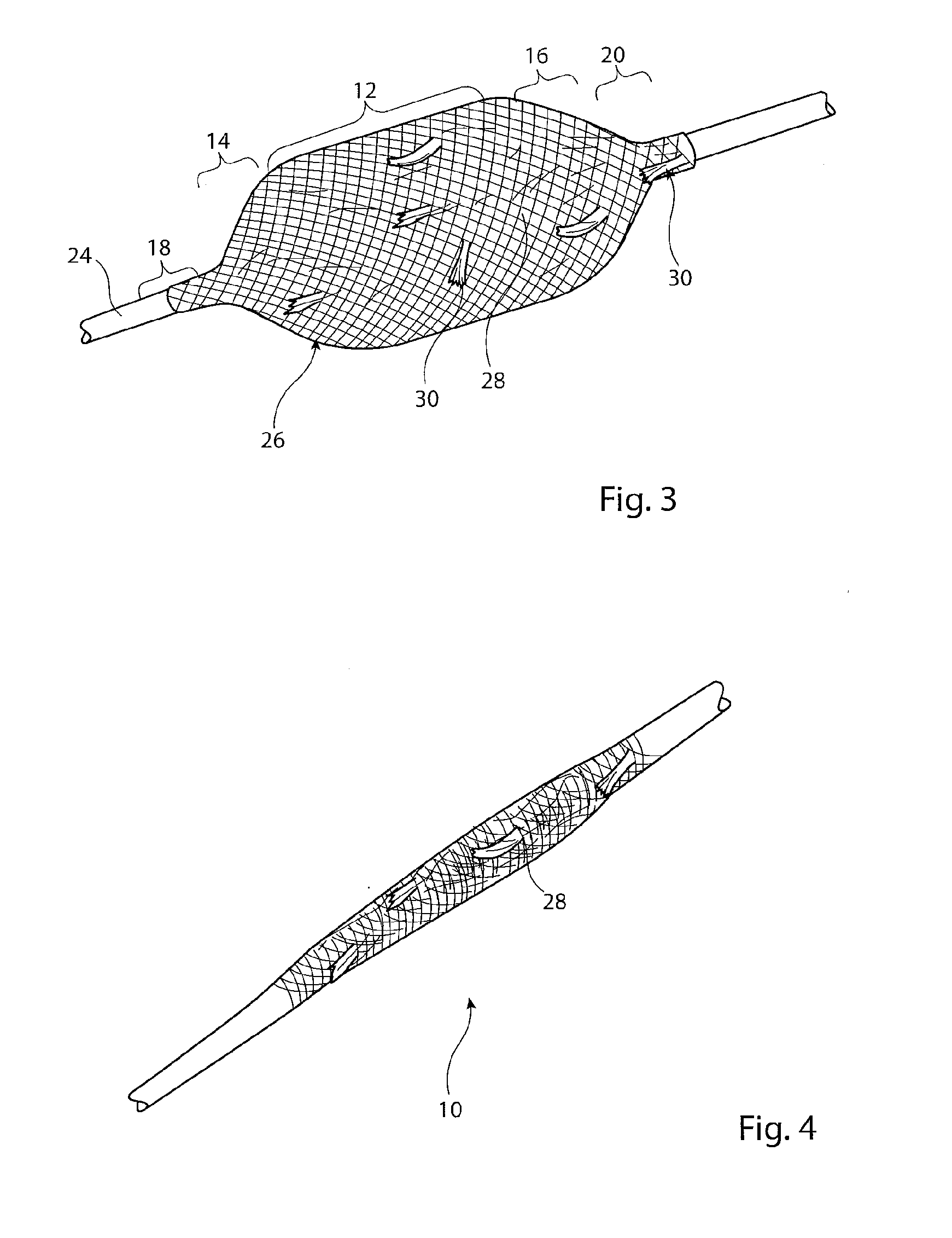
[0035]Referring to FIGS. 1 and 2, there is shown an embodiment of frame for an occluder assembly as taught herein. The frame 10 has a central generally cylindrical body portion 12 bounded by first and second tapered portions 14, 16 which end in frame extremities 18, 20. The frame 10 is formed from a wire braid, as are the tapered portions 14, 16. The extremities 18, 20 may equally be formed of braided wire, as extensions to the parts 12-16, but in other embodiments are tubular elements fixed to the braided wire, for instance by welding, soldering, bonding or any other suitable method.

[0036]As can be seen in particular in the cross-sectional view of FIG. 1, extending inside the frame 10 between the first and second extremities 18, 20, is a sprung element 22, in the example shown a coil spring. The sprung e...


PUM


Abstract

A vascular occluder includes a frame (10) having a generally cylindrical body portion (12), first and second end conical portions (14, 16) and first and second extremities (18, 20). Located within the fame (10) is a fibrous barrier (28) which provides rapid occlusion. The extremities (18, 20) are coupled by a coil spring (22) which acts to pull the extremities (18, 22) towards one another and thereby to cause longitudinal contraction an consequential radial expansion of the frame (10). The coil spring (22) ensures rapid and reliable deployment of the occluder in a patient's vessel. The occluder also can be compressed to a narrow diameter for deployment by means of narrow diameter sheaths.

Description

[0001]This application claims the benefit of the filing date of United Kingdom (GB) patent application number 1210562.3, filed Jun. 14, 2012, which is hereby incorporated by reference herein.TECHNICAL FIELD[0002]The present invention relates to a vascular occlusion device and to an introducer assembly including such a device.BACKGROUND ART[0003]In a number of medical conditions and surgical procedures it is required or advisable to occlude a patient's vessel, be it temporarily or long term. For this purpose, vascular occlusion devices are known which are able to be deployed endoluminally in a patient. A variety of occlusion devices is known, including devices which provide substantially instantaneous occlusion, by means of an impermeable barrier, to devices which achieve occlusion over time, particularly by promoting blood clotting at the device, which blood clotting provides the desired occlusion of the vessel.[0004]Endoluminal delivery of medical devices requires the meeting of a ...

Claims


Application Information

Patent Timeline
Patent Type & Authority Applications(United States)
IPC IPC(8): A61B17/12
CPCA61B17/12109A61B17/12177A61B17/12168
Inventor CLAUSEN, JACOB LUNDHENDRIKSEN, PERJOHNSEN, JEPPE BOECKHAUSLUNDSTEEN, NICHOLAS GULMANNOEHLENSCHLAEGER, BENT
Owner COOK MEDICAL TECH LLC
Why Eureka
Try Eureka