Eureka AIR delivers breakthrough ideas for toughest innovation challenges, trusted by R&D personnel around the world.

Supplying/removing apparatus of puncture sealant of tire

a technology of puncture sealant and suction apparatus, which is applied in the direction of liquid transfer device, packaging goods type, liquid handling, etc., can solve the problems of difficulty in repeatedly compressing and restoring containers, and the requirement of suction apparatus for removing sealants separately, so as to achieve no increase in apparatus cost and no complicated apparatus structure

Inactive Publication Date: 2005-12-29
SUMITOMO RUBBER IND LTD
View PDF2 Cites 50 Cited by
  • Summary
  • Abstract
  • Description
  • Claims
  • Application Information

AI Technical Summary

Benefits of technology

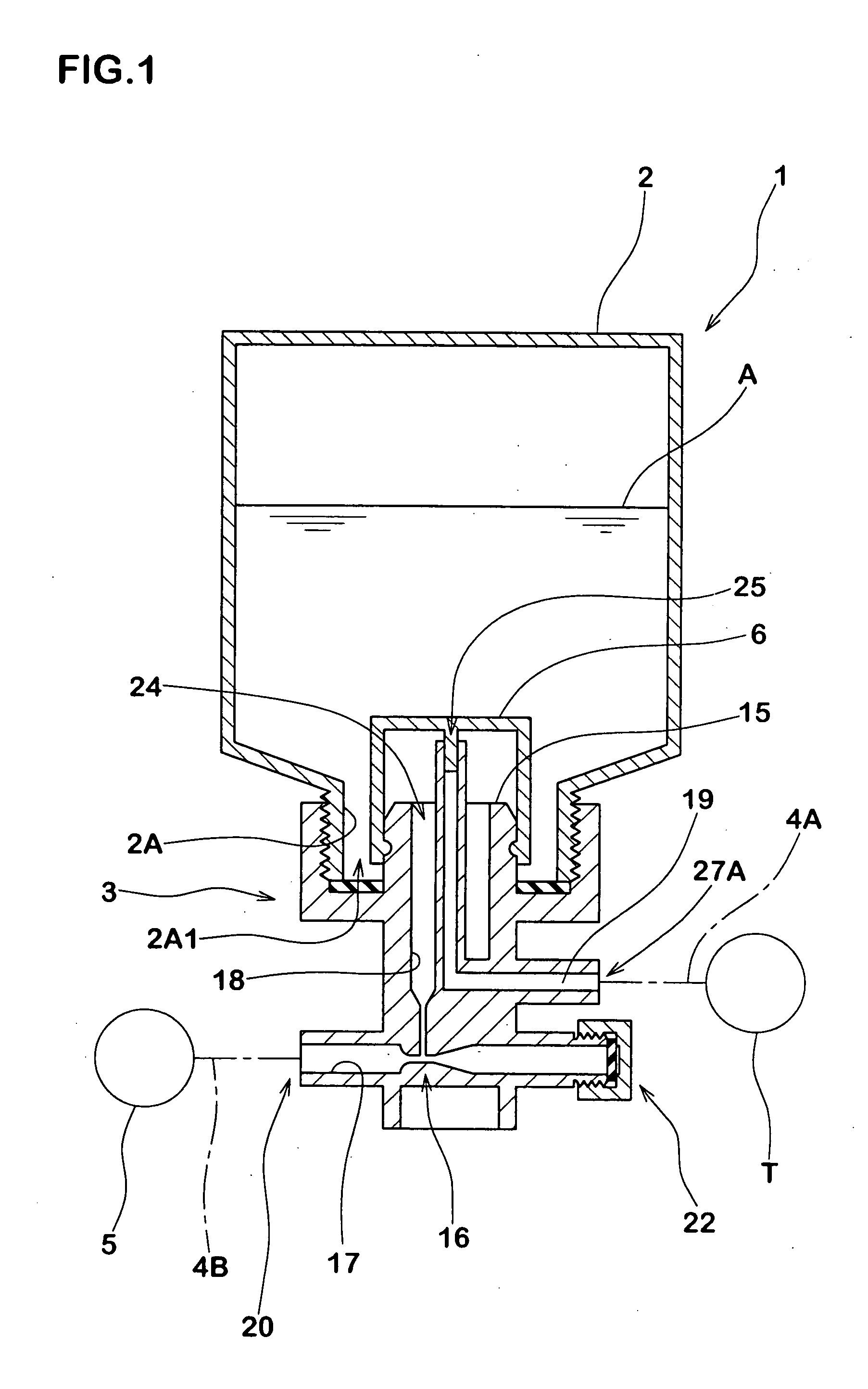
[0008] The present invention basically uses, as an air flow-path, a venturi flow-path having a venturi portion at which its diameter is reduced. Based on this structure, it is an object of the invention to provide an economical supplying / removing apparatus of a puncture sealant of a tire capable of switching between a charging operation and a removing operation of a puncture sealant with a single motion, in which the apparatus cost is not increased, the apparatus structure is not complicated, the apparatus can be used easily, and a suction apparatus exclusively used therefor is not required.
[0015] Since the present invention has the above-described structure, it is possible to exhibit both a charging function and a removing function of the puncture sealant in an automatic system without increasing the cost of the apparatus or complicating the structure of the apparatus, and added value is enhanced, and usability can be enhanced. A special-purpose sucking apparatus is unnecessary, and the invention can greatly contribute economically.

Problems solved by technology

According to the automatic system, however, since the pressure-resistant container having high strength is used, it is difficult to repeatedly compress and restore the container unlike the manual system.
Thus, the automatic system has a problem that a suction apparatus for removing sealant is required separately.

Method used


Image

  • Supplying/removing apparatus of puncture sealant of tire
  • Supplying/removing apparatus of puncture sealant of tire
  • Supplying/removing apparatus of puncture sealant of tire

Examples


Embodiment Construction

[0022] An embodiment of the present invention will be explained below together with illustrated examples.

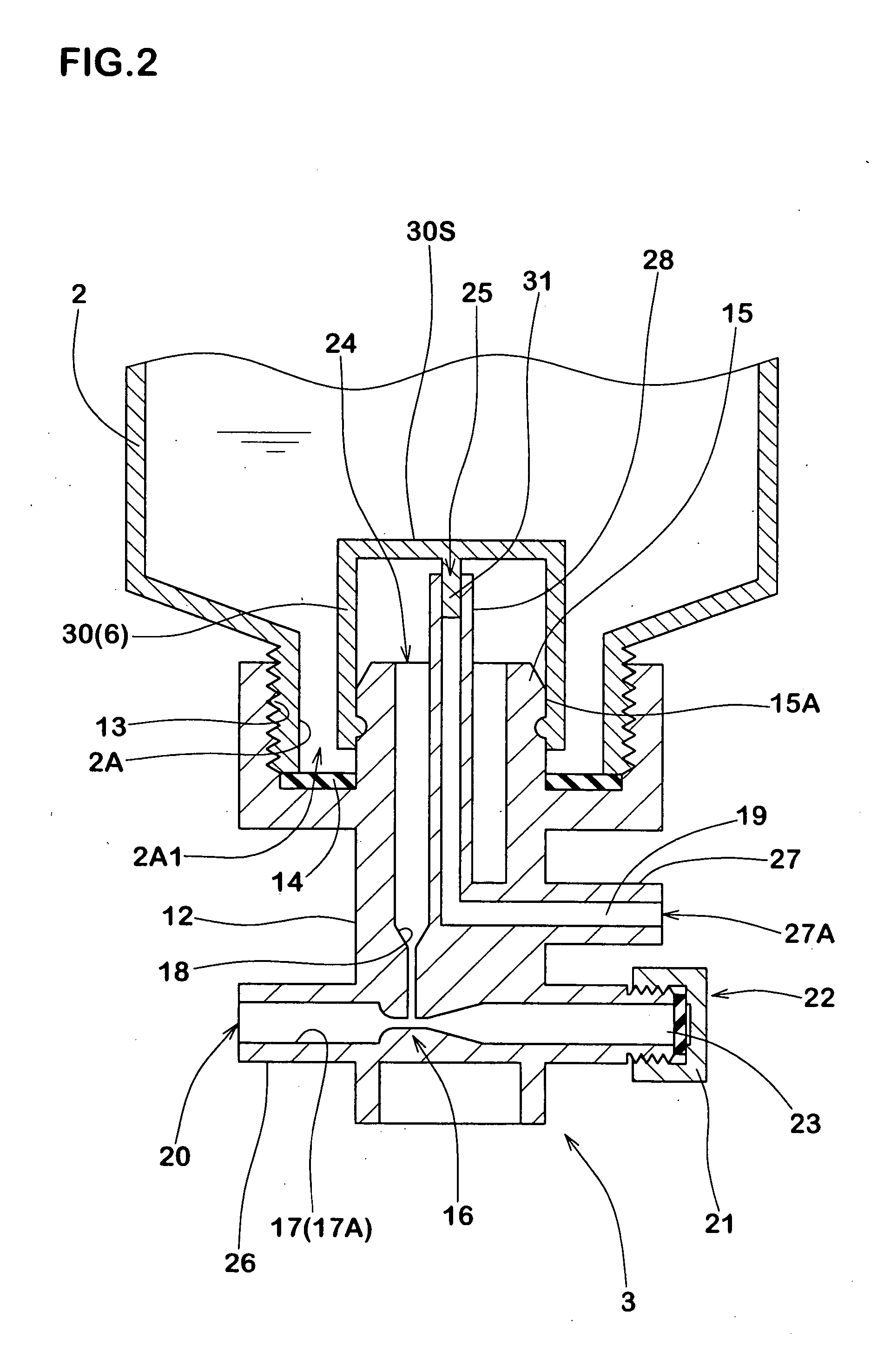
[0023]FIG. 1 is a sectional view showing a case in which a supplying / removing apparatus of a puncture sealant of the present invention is used for repairing a puncture in a first-aid manner. FIG. 2 is an enlarged sectional view of an essential portion of FIG. 1.

[0024] As shown in FIG. 1, a puncture sealant supplying / removing apparatus 1 (apparatus 1, hereinafter) includes a pressure-resistant bottle 2 capable of accommodating a puncture sealant A, an apparatus body 3 capable of amounting the pressure-resistant bottle 2, a supply hose means 4A for supplying (or removing) the puncture sealant A in the pressure-resistant bottle 2 into a tire (T), and a high pressure air source 5.

[0025] The pressure-resistant bottle 2 is a bottle-like pressure-resistant container having pressure resistance of 800 kPa or higher. The pressure-resistant bottle 2 has a neck 2A, and a taking-out openin...


PUM

PropertyMeasurementUnit
opening diameteraaaaaaaaaa
pressureaaaaaaaaaa
pressureaaaaaaaaaa

Abstract

A puncture sealant supplying / removing apparatus includes a pressure-resistant bottle, an apparatus body on which the pressure-resistant bottle can be mounted, supply hose means which supplies or returns a puncture sealant accommodated in the pressure-resistant bottle to or from a tire, and a high pressure air source. The apparatus body comprises a venturi flow-path having a venturi portion, a first flow-path extending from the venturi portion into the pressure-resistant bottle, and a second flow-path extending from an inside of the pressure-resistant bottle and connected to one end of the supply hose means. The venturi flow-path is provided at its one end with an air intake which is connected to the high pressure air source, the venturi flow-path is provided at its other end with an opening / closing tool capable of opening and closing the other end.

Description

BACKGROUND OF THE INVENTION [0001] 1. Field of the Invention [0002] The present invention relates to a supplying / removing apparatus of puncture sealant of a tire capable of charging the puncture sealant into a punctured tire and removing the puncture sealant charged in the tire. [0003] 2. Description of the Related Art [0004] As such an apparatus, Japanese Patent Applications Laid-open No. 2003-127242 and No. 2004-114524 propose structures as shown in FIGS. 6(A) and (B). In this apparatus (a), an easily deformable plastic container (b) is used, the container (b) is manually compressed (pressed), thereby charging the puncture sealant into a tire (T) (FIG. 6(A)). Thereafter, the container (b) is taken out, a compressor is connected to the tire (T) to pump up the tire (T) and then, the tire (T) is allowed to run, and the puncture hole is sealed by the puncture sealant in a first-aid manner. This method is called a manual system in some cases. [0005] The tire (T) which was repaired in t...

Claims


Application Information

Patent Timeline
Patent Type & Authority Applications(United States)
IPC IPC(8): B29C73/02B29C73/16B67D7/02
CPCB29C73/025B67D7/0266B29C73/166B29L2030/00
Inventor KOJIMA, YOSHIHIDEKUBOTA, YASUHIRO
Owner SUMITOMO RUBBER IND LTD
Why Eureka
Eureka Blog
Learn More