
Tray and chassis blade server architecture

Inactive Publication Date: 2013-12-19
MICROSOFT TECH LICENSING LLC
View PDF2 Cites 35 Cited by
  • Summary
  • Abstract
  • Description
  • Claims
  • Application Information

AI Technical Summary

Benefits of technology

This patent describes a computer server design that allows for easy customization and integration of different types of blades. The server is housed in a chassis that provides power and network connectors, and the blades can be easily inserted and connected. The chassis can also have interconnections between different types of blades, and a management interface that allows for easy addition, enumeration, exploration, and configuration of blades. Overall, this design provides flexibility and efficiency for servers and data centers.

Problems solved by technology

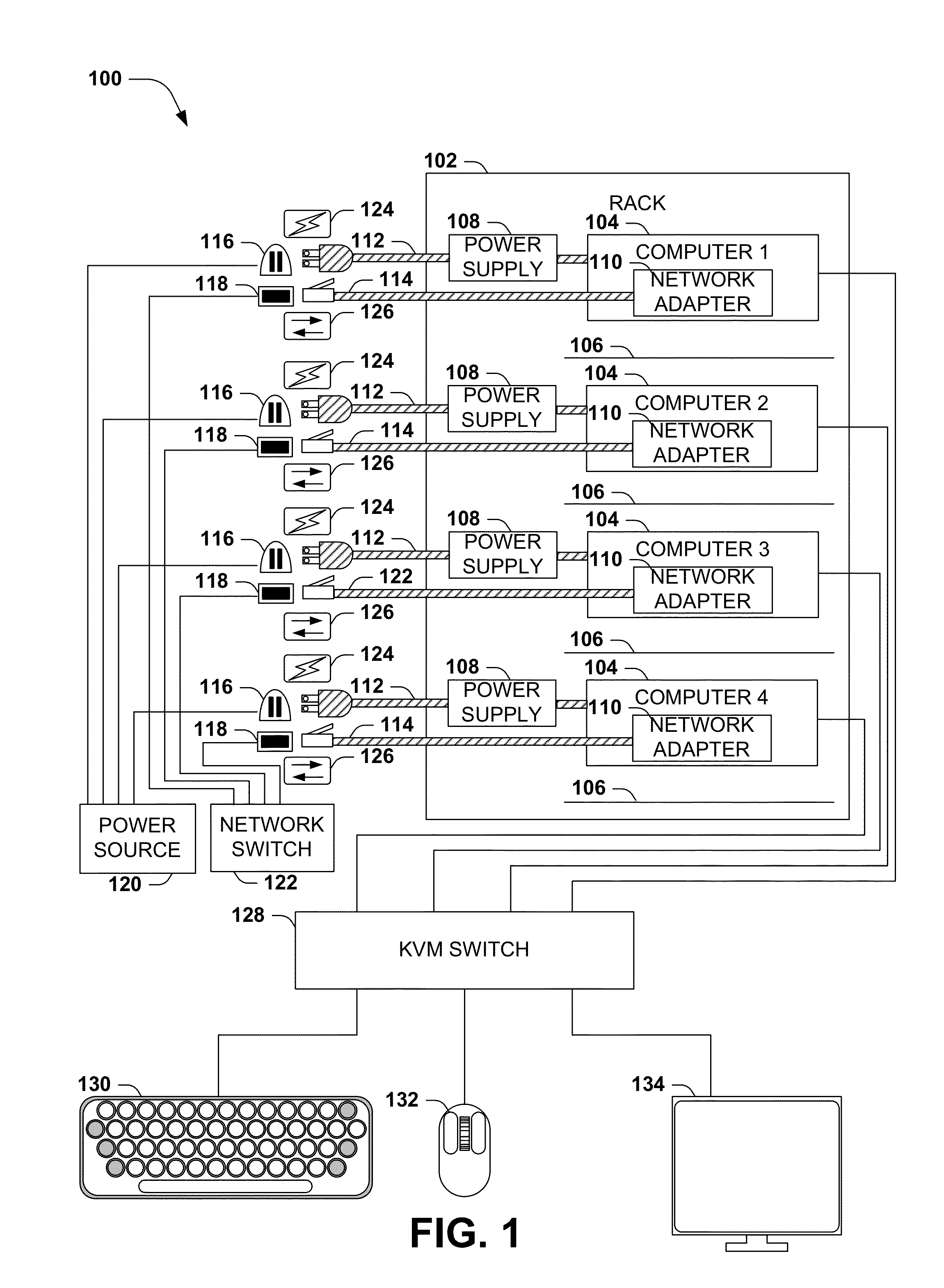
However, the rack 102 in the exemplary scenario 100 of FIG. 1, and many similar devices, may present some limitations.
As a second example, the power cable 112 and the network cable 114 consume space; may involve an extra expense of resources; and / or may represent an additional point of failure.
As a fifth example, the shelves 106 may enable only limited height adjustments, and may therefore fail to accommodate a computer 104 with extra height and / or may present excess space around a computer 104, thus presenting a space inefficiency.
These and other disadvantages may result from racks 102 and other enclosures of multi-blade computational units.
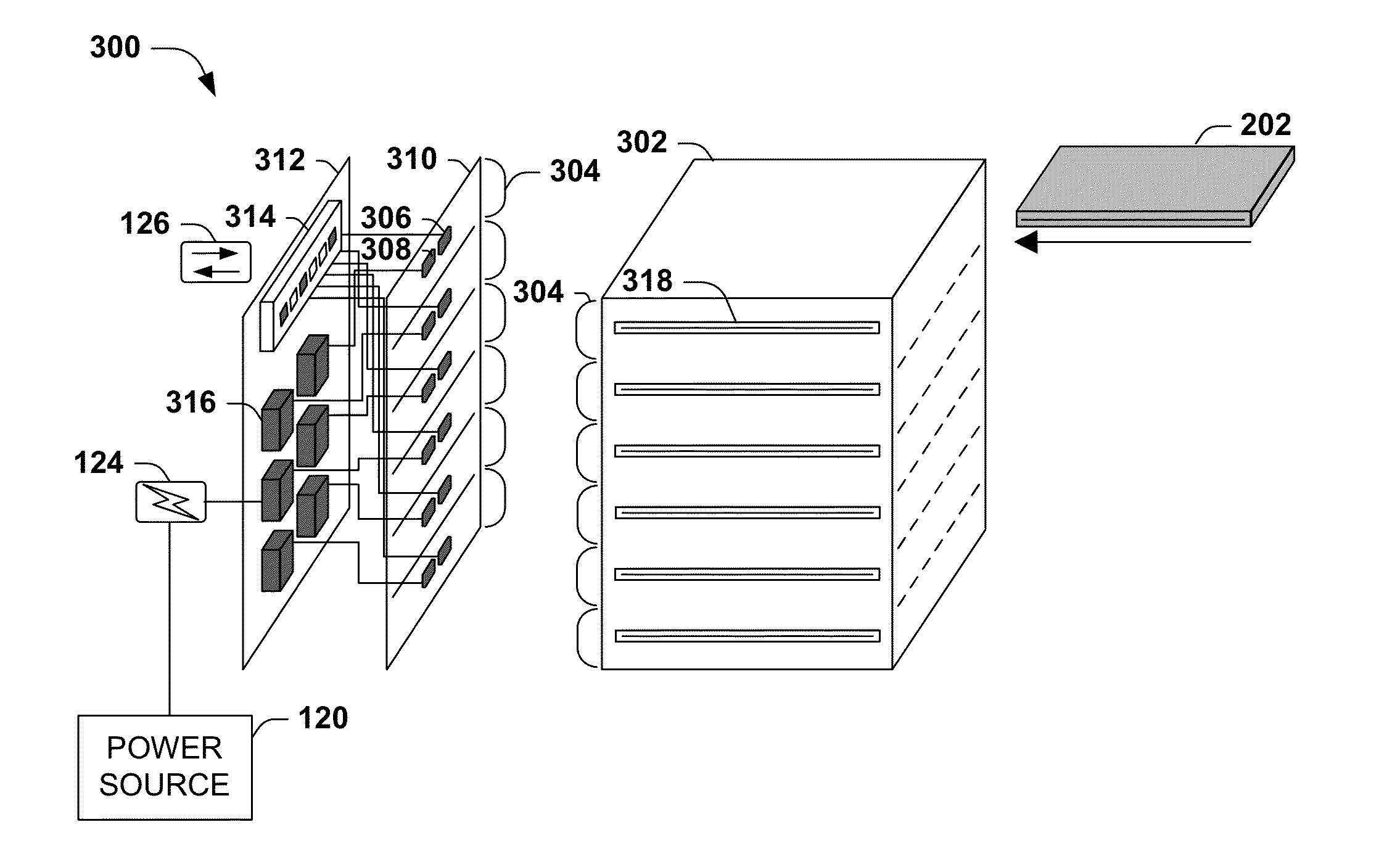
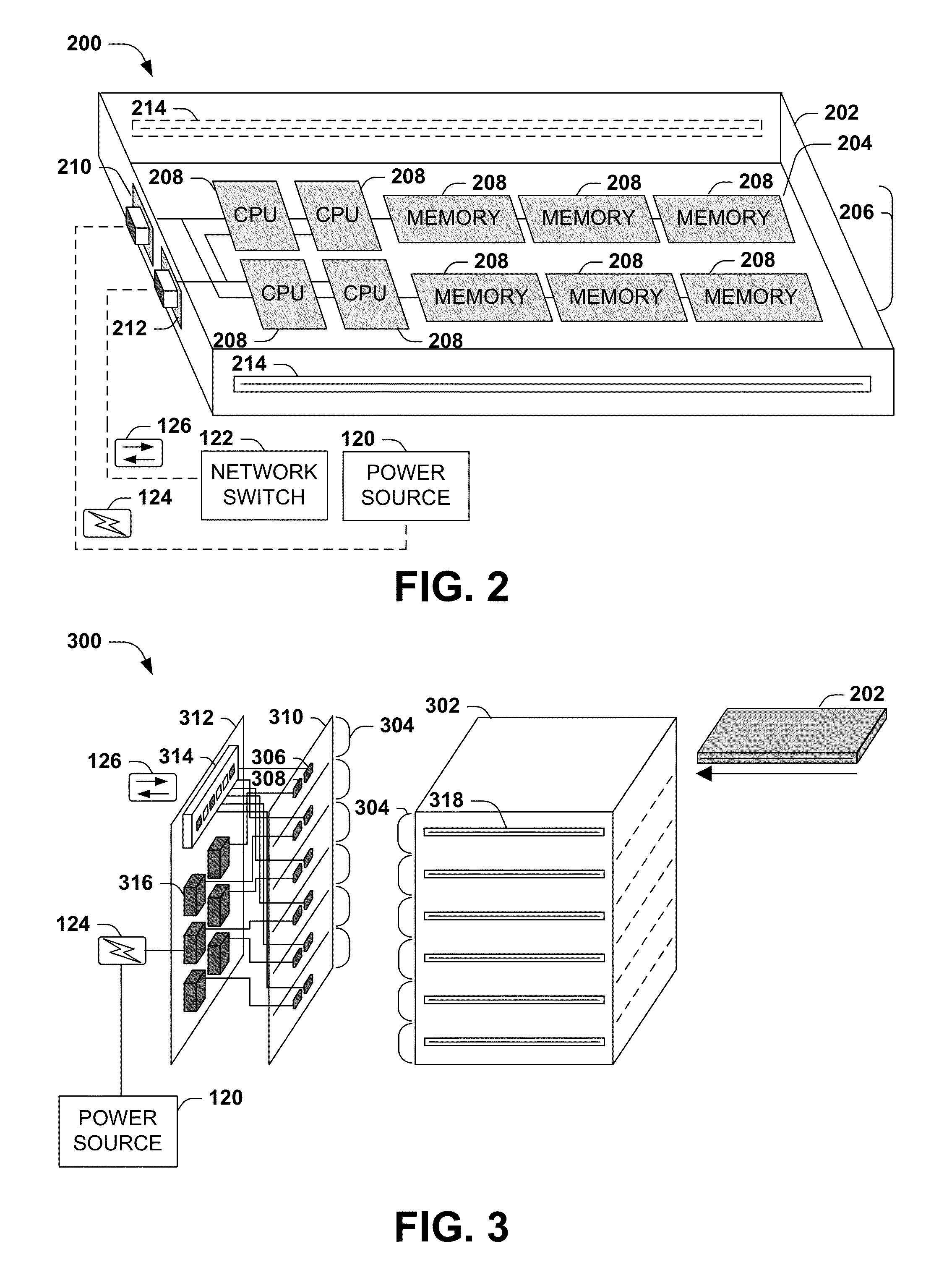
The guides may enable the insertion of the tray in position to couple the connectors without manual intervention, even correcting a small amount of misalignment of the connectors, and may block incorrect insertion of the tray in a manner that may otherwise fail to achieve connection and / or may damage the connectors.

Method used


Image

  • Tray and chassis blade server architecture
  • Tray and chassis blade server architecture
  • Tray and chassis blade server architecture

Examples


Embodiment Construction

[0014]The claimed subject matter is now described with reference to the drawings, wherein like reference numerals are used to refer to like elements throughout. In the following description, for purposes of explanation, numerous specific details are set forth in order to provide a thorough understanding of the claimed subject matter. It may be evident, however, that the claimed subject matter may be practiced without these specific details. In other instances, structures and devices are shown in block diagram form in order to facilitate describing the claimed subject matter.

A. INTRODUCTION

[0015]Within the field of computing, many scenarios involve a server comprising a plurality of computational units. As a first example, the server may comprise a set of independently operable computers configured to intercommunicate to achieve a task in a cooperative manner, such as a server farm or a peer-to-peer processing network. As a second example, the server may comprise a set of computation...


PUM


Abstract

In computing scenarios involving an aggregation of multiple computational units into a server or computer set, many architectures may be devised to provide physical storage and logical aggregation of the computational units. Presented herein are variations of one such architecture, comprising a chassis having a set of slots, into which may be inserted a tray storing the computational units of one or more blades. Respective trays and chassis slots comprise a power connector and a network connector that are positioned to connect directly (i.e., without a cable or manual interaction) when a tray is inserted into a slot. The chassis stores a set of power supplies, and may connect each blade with a power supply, optionally providing power routing and failover capabilities. The chassis may also provide a management component that connects to and provides management capabilities of the blades of the trays, power supplies, and climate regulating components.

Description

BACKGROUND[0001]Within the field of computing, many scenarios involve a multi-blade computational unit architecture comprising a support structure configured to store a set of modular computing units. As a first example, a rack server may comprise a set of racks, each sized to hold a computational unit, such as a cased or caseless mainboard including a processor, memory, a power supply, and one or more storage devices, network adapters, and other expansion cards. The mainboard may include a power supply having a power inlet (usually positioned toward the back of the unit) that may be attached to a power outlet of the rack via a power cable, and a network port that may be attached to a network port of the rack using a network cable. As a second example, a blade server may comprise a set of slots, wherein a structural unit may comprise a set of parallel slots respectively configured to receive a computational unit of a “blade” form factor (e.g., a thin, substantially planar array of c...

Claims


Application Information

Patent Timeline
IPC IPC(8): H05K7/16G06F1/16
CPCG06F1/183G06F1/189H05K7/1488
Inventor SHAW, MARKFAIST, MATTHEW ALLENPETERSON, ERIC C.ROGERS, HARRY RAYMONDKHESSIB, BADRIDDINEVAID, KUSHAGRA VIRENDRAKUMAR
Owner MICROSOFT TECH LICENSING LLC
Learn More