
Method of and base station for controlling beam forming in a mobile cellular network

a mobile cellular network and beam forming technology, applied in the field of mobile cellular networks, can solve the problems of unavoidable spatial interference and possible bandwidth problems, and achieve the effect of improving the beam forming in the mobile cellular network

Inactive Publication Date: 2011-11-08
WSOU INVESTMENTS LLC
View PDF5 Cites 23 Cited by
  • Summary
  • Abstract
  • Description
  • Claims
  • Application Information

AI Technical Summary

Benefits of technology

"The present invention provides an improved method for controlling beam forming in a mobile cellular network. The method selects beam pattern sequences from a predefined set of beam pattern sequences and applies them on each sector of a cell. The trigger base station informs all neighbored base stations about the sequent change of the beam subsets used for communication with mobile units to synchronize the sequent change. The mobile units and base stations can select in advance a filter technique to remove inter-cell and intra-cell spatial interference. The technical effects of the invention include reducing interference, improving signal quality, and increasing throughput for mobile units."

Problems solved by technology

A general problem of mobile cellular networks is signal quality which can be described in the signal-to-interference-plus-noise ratio (SINR).
Thus, bandwidth problems may arise due to interference problems originating from a limited frequency band available for communicating in the mobile cellular network.
However, if two mobile units are located close to each other and communicate with similar radio frequencies, spatial interference is unavoidable.

Method used


Image

  • Method of and base station for controlling beam forming in a mobile cellular network
  • Method of and base station for controlling beam forming in a mobile cellular network
  • Method of and base station for controlling beam forming in a mobile cellular network

Examples


Embodiment Construction

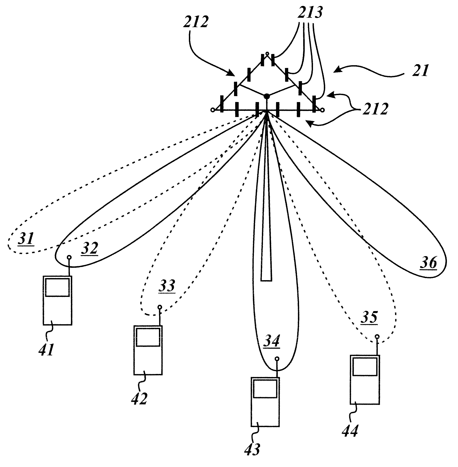
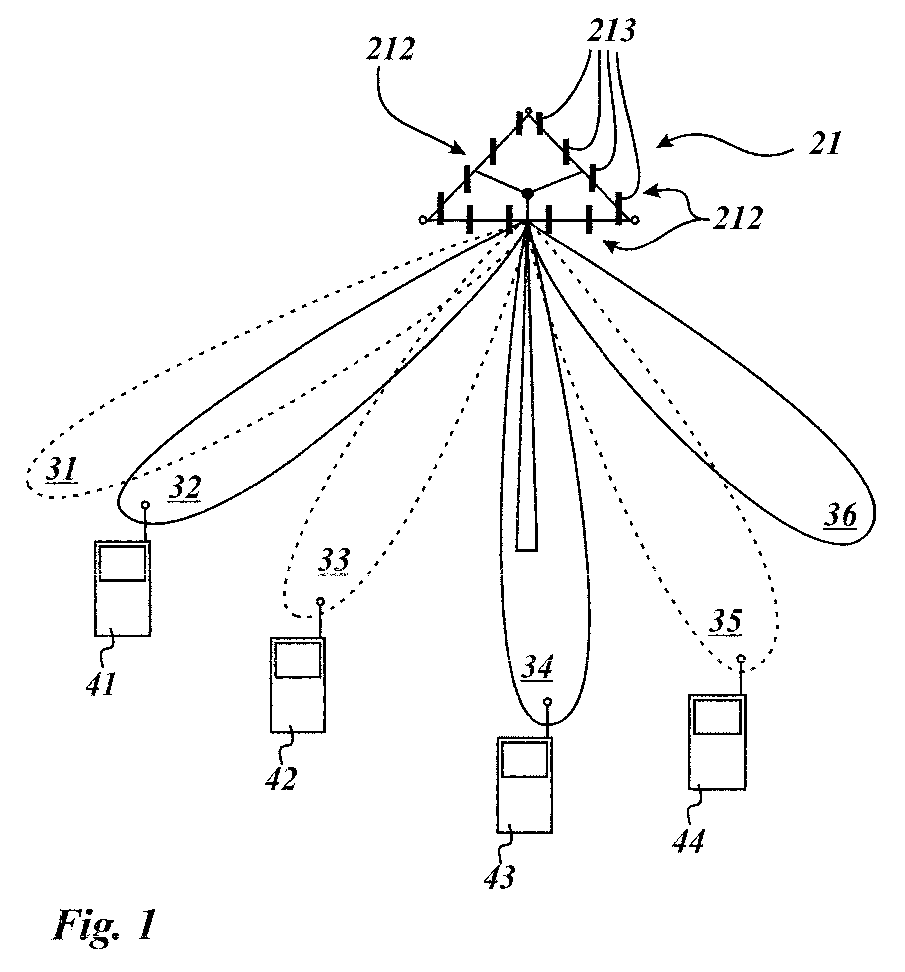
[0030]FIG. 1 shows a base station 21 and four mobile units 41, 42, 43, 44 in one sector of a cell of a mobile cellular network. The base station 21 comprises three antenna units 212 wherein each of the antenna units 212 is assigned to a different sector of the cell. Each antenna unit 212 is formed of a linear antenna array with four equal linear antenna elements 213 arranged in parallel. The front antenna unit 212—in the following just called antenna unit 212—provides mobile cellular communication to the mobile units 41, 42, 43, 44 by means of beams 31, 32, 33, 34, 35, 36. The antenna unit 212 is able to apply the beams 31, 32, 33, 34, 35, 36 on the respective sector of the cell of the cellular mobile network under control of a control unit. Furthermore, the control unit of the base station 21 is adapted to execute the method of controlling beam forming in a mobile cellular network.

[0031]The control unit of the base station 21 is adapted to control the beam forming of the antenna un...


PUM


Abstract

The invention concerns a melhod and a base station for controlling beam forming in a mobile cellular network: Antenna units apply a respective beam pattern sequence on each sector of a cell served by the respective base station. A base station acts as trigger base station informing all neighbored base stations of the cluster not to change their beam pattern sequences. The trigger base station changes the beam pattern sequence applied on the sectors of its cell. The trigger base station triggers one or more mobile units to calculate signal quality parameters for currently applied beam pattern sequence. The trigger base station selects an optimal beam pattern sequence from the set based on the calculated signal quality parameters and applies as a new beam pattern sequence on the respective sector.

Description

[0001]The invention is based on a priority application EP 08 290 502.7 which is hereby incorporated by reference.TECHNICAL FIELD[0002]The present invention relates to a method of and a base station for controlling beam forming in a mobile cellular network.BACKGROUND OF THE INVENTION[0003]The technical field of the present invention is directed to mobile cellular networks, in particular to improving of quality of service provided by base stations to mobile units, which access the base stations of the mobile cellular network by means of a wireless link. For instance, the method and the base station of the present invention are applicable to WiMAX (WiMAX=Worldwide Interoperability for Microwave Access), 3GPP LTE (3GPP LTE=3rd Generation Partnership Project Long Term Evolution) and systems beyond 3G (3G=3rd Generation).[0004]A general problem of mobile cellular networks is signal quality which can be described in the signal-to-interference-plus-noise ratio (SINR). A typical mobile cellu...

Claims


Application Information

Patent Timeline
Patent Type & Authority Patents(United States)
IPC IPC(8): H04M1/00
CPCH01Q1/246H04B7/0617H04B7/0695H04W16/28H04B7/0408H04B7/0491H04W84/042H04W88/08H04L25/0224
Inventor WILD, THORSTEN
Owner WSOU INVESTMENTS LLC
Learn More