Electronic ignition system for an engine of a vehicle in case of failure

a technology of electronic ignition system and engine, applied in the field of electronic ignition system, can solve the problems of serious failure of the phase of charging the primary winding of the coil, and failure of the engine or of different engine components, so as to achieve accurate control, fast activation, and discharge the energy stored

Active Publication Date: 2013-12-19
STMICROELECTRONICS SRL
View PDF2 Cites 20 Cited by
  • Summary
  • Abstract
  • Description
  • Claims
  • Application Information

AI Technical Summary

Benefits of technology

[0021]it reduces the time interval between the instant wherein the failure is detected and the instant wherein the voltage drop across the primary winding is clamped to a predetermined value, thus allowing a fast activation of the protection systems (for example, of the thermal type) and thus preventing the current flowing through the primary winding from reaching high peak values (in the example of the thermal-type, the device is prevented from reaching high temperatures);

Problems solved by technology

Moreover, the spark can occur only at the instants calculated by the control unit because, otherwise, serious failures in the engine or to different engine components can occur.
It is possible that failures occur during the phase of charging the primary winding of the coil.
The shut-down of the electronic ignition should occur safely, that is it's necessary to discharge the energy stored into the primary winding for preventing the spark from occurring between the plug electrodes at time instants different from those calculated by the control unit; in fact, as previously explained, the spark can occur only at particular instants calculated by the control unit, otherwise serious failures can occur to the engine or to different engine components.
This known solution has the above mentioned disadvantage of requiring a long time interval between the instant wherein the failure is detected and the time instant wherein the current value through the primary winding of the coil (and thus the value of the voltage drop across the primary winding) starts decreasing.
This known solution has the previously indicated disadvantage of requiring a long time interval between the instant wherein the failure is detected and the time instant wherein the current value through the coil primary winding (and thus the value of the voltage drop across the primary winding) starts decreasing; during this time interval having a high value the charge current continues to further increase

Method used


Image

  • Electronic ignition system for an engine of a vehicle in case of failure
  • Electronic ignition system for an engine of a vehicle in case of failure
  • Electronic ignition system for an engine of a vehicle in case of failure

Examples


Embodiment Construction

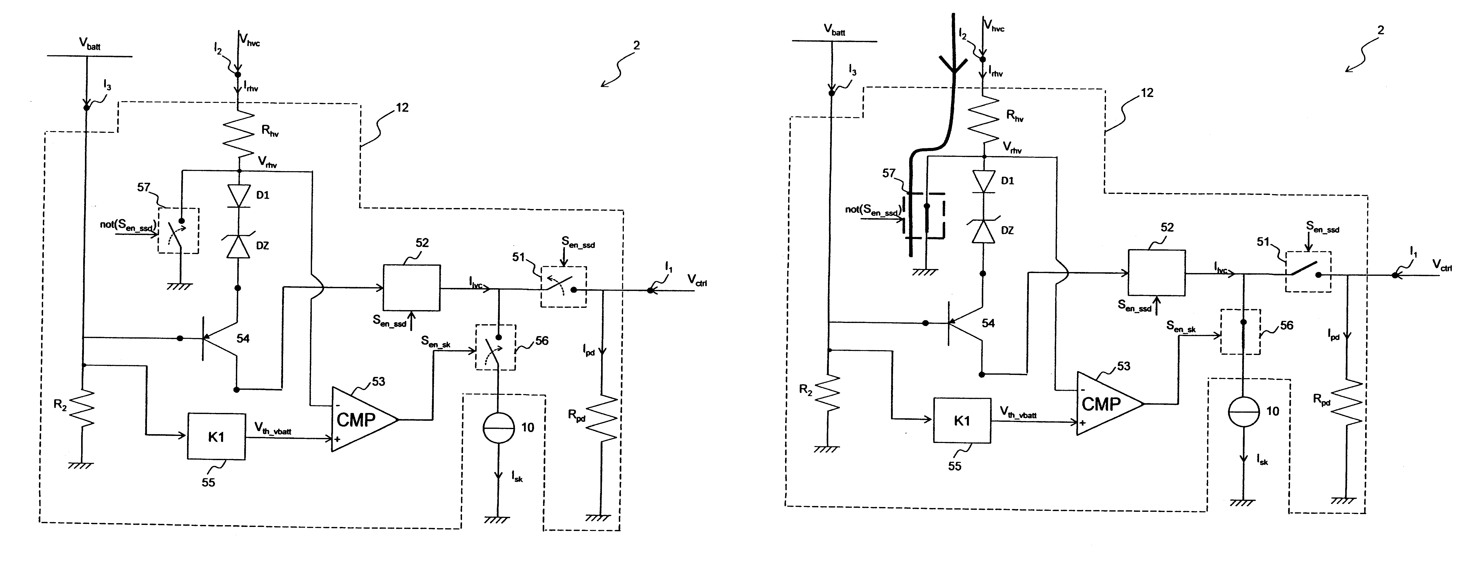
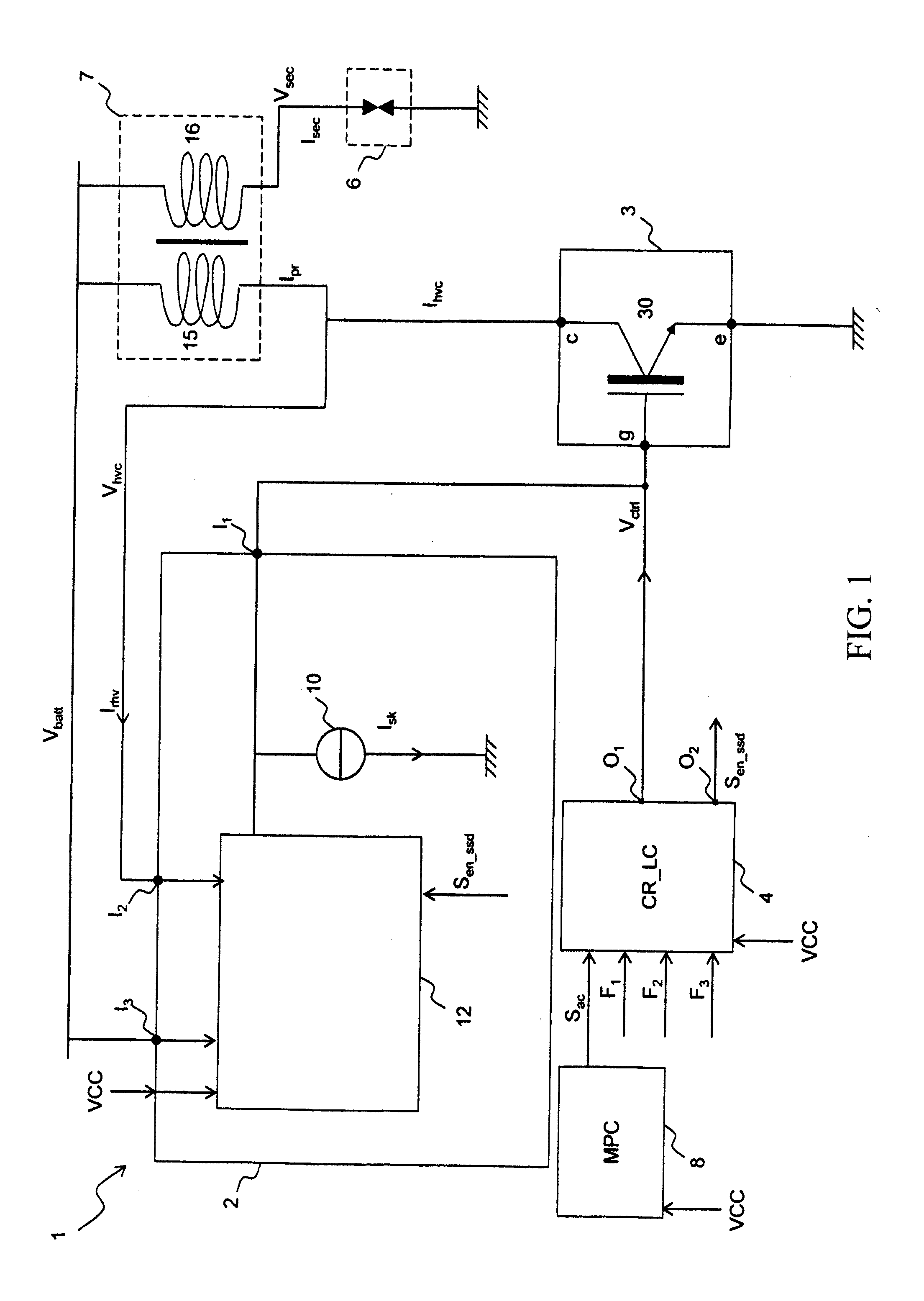
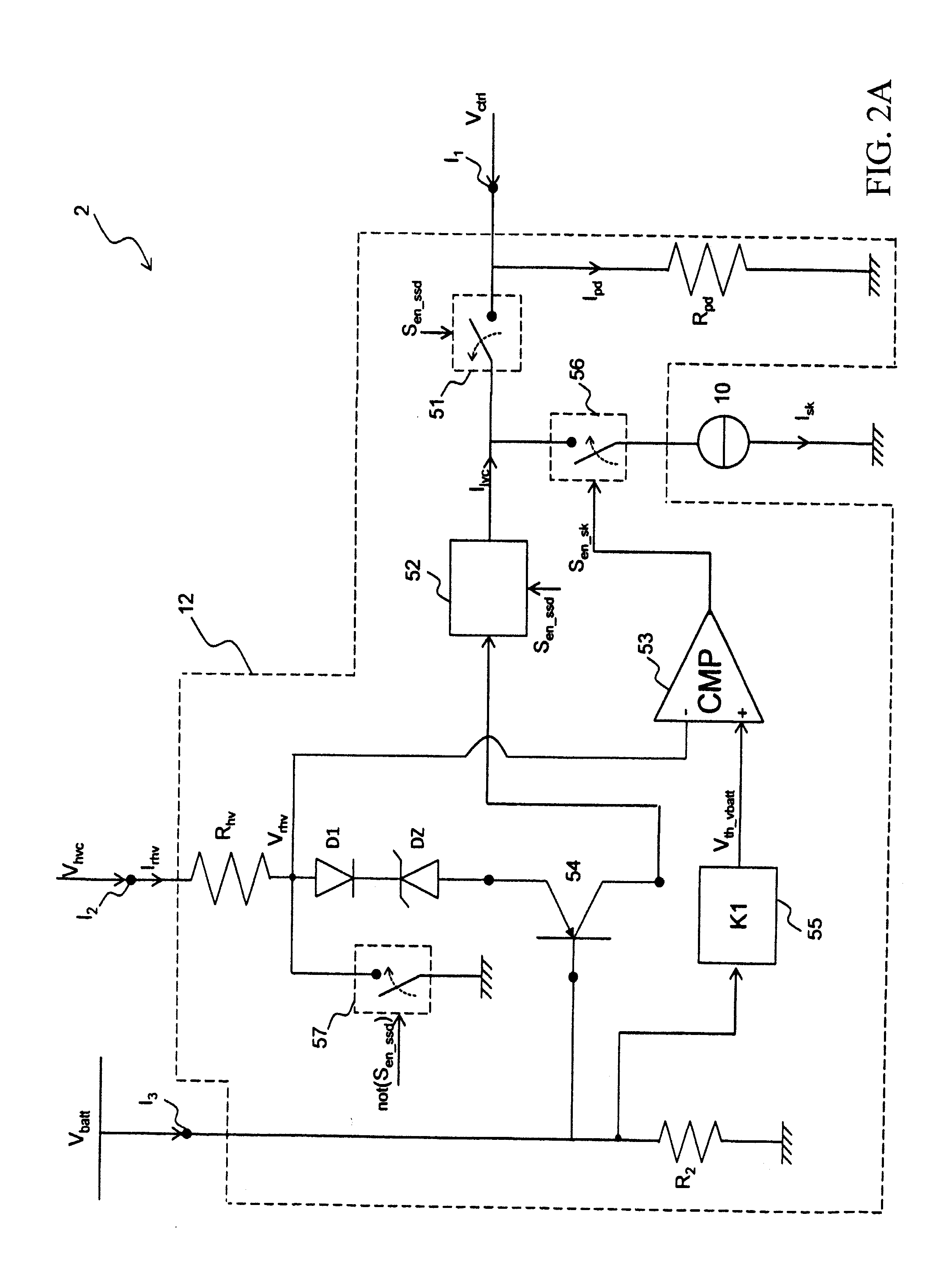
[0032]With reference to FIG. 1, there is shown an electronic ignition system 1 for the engine of a vehicle (for example, a car) according to an embodiment.

[0033]The electronic ignition system 1 comprises a coil 7, a switch 3, a spark plug 6, a microprocessor 8, a logic circuit 4, and an electronic protection circuit 2.

[0034]The microprocessor 8, the logic circuit 4 and the electronic protection circuit 2 are supplied by a low supply voltage VCC (for example, the VCC value is comprised between 3.3 V and 5 V).

[0035]The electronic ignition system 1 is such to have a charging phase, a turn-on phase and a safety discharging phase.

[0036]In the charging and turn-on phases the electronic protection circuit 2 is disabled and in the safety discharging phase the electronic protection circuit 2 is enabled.

[0037]During the charging phase the coil 7 primary winding 15 stores energy and in the turn-on phase the spark between the electrodes of the plug 6 is generated, thus burning the air / fuel mixt...


PUM


Abstract

An electronic system to discharge a transformer in case of a failure during a charging phase of the transformer. The system includes the transformer having a primary winding with a first terminal connected to a battery voltage and with a second terminal for generating a primary voltage signal, includes a switch serially connected to the primary winding and having a control terminal carrying a control voltage signal for opening or closing the switch and includes an electronic circuit. The electronic circuit further includes a current generator and a voltage clamping.

Description

CROSS REFERENCE TO RELATED APPLICATIONS[0001]This application claims the priority benefit of Italy patent application serial number MI2012A000893, filed on May 23, 2012, which is hereby incorporated by reference to the maximum extent allowable by law.BACKGROUND[0002]1. Technical Field[0003]The present disclosure generally relates to the electronics field. More in particular, the present disclosure concerns an electronic ignition system for an engine of a vehicle in case of failure during a charging phase of the the coil.[0004]2. Discussion of the Related Art[0005]It is known that most of the electronic ignition systems for the engine of motor vehicles are of the inductive-type. An inductive-type ignition system comprises a battery for supplying energy, a coil having a primary winding with a terminal connected to the battery, a switch connected between the other terminal of the primary winding and ground and a spark plug connected to the secondary winding of the coil. The coil is a t...

Claims


Application Information

Patent Timeline
IPC IPC(8): H02H9/04
CPCH02H9/041F02D41/1479F02P3/051F02P3/055F02P9/002F02D41/00H03K17/166H03K17/168
Inventor TRECARICHI, CALOGERO ANDREATORRISI, GIOVANNI LUCATAGLIAVIA, DONATO
Owner STMICROELECTRONICS SRL
Why Eureka
Try Eureka