Bonded-magnet rotor, method of manufacturing thereof, and motor provided therewith

a technology of bonded magnets and rotors, which is applied in the direction of magnetic circuit rotating parts, magnetic bodies, magnetic circuit shapes/forms/construction, etc., can solve the problems of reducing the fracture strength of bonded magnets, the dimension accuracy of the rotor is less stable, and the expansion of bonded magnets in excess of their limit during press fitting, etc., to reduce the phase misalignment of the pole position, the effect of minimizing the gap and reducing the misal

Active Publication Date: 2013-12-12
PANASONIC INTELLECTUAL PROPERTY MANAGEMENT CO LTD
View PDF2 Cites 0 Cited by
  • Summary
  • Abstract
  • Description
  • Claims
  • Application Information

AI Technical Summary

Benefits of technology

This patent describes a bonded-magnet rotor for a motor that reduces phase misalignment between polar positions and improves motor efficiency. The bonded-magnet rotor is made by pressure-welding and bonding the magnets to the rotor core to create a nearly zero-thickness bonding layer. The position of the magnets can be easily clarified, allowing for accurate positioning and reducing the gap between the stator and rotor. The motor has a high working point, and its high efficiency results in a compact motor with improved performance.

Problems solved by technology

In this case, the press fitting is carried out in such a way that the ring-shaped bonded magnet is expanded in the radial direction, which results in an expansion of the bonded magnet in excess of its limit during press fitting.
As a result, there has been a practical problem, e.g. a fracture of the bonded magnet in manufacturing, and a decrease in fracture strength of the bonded magnet.
For this reason, there has been another problem that dimension accuracy of the rotor is less stable.
Furthermore, in forming the conventional rotor, there has been still another problem that, when forming the rotor, it is difficult to carry out precise phase-alignment between magnetizing positions of main magnet pieces and a magnetizing position of a magnet piece for positioning.
In addition, in the bonding process, there exist problems particular to adhesive, for example, variations in accuracy of bonding positions of the respective magnet pieces, eccentricities due to a bonding misalignment, and variations in outside diameters caused by variations in bonding thickness.
As a result, there has been a problem that it is difficult to form the rotor with high accuracy.

Method used


Image

  • Bonded-magnet rotor, method of manufacturing thereof, and motor provided therewith
  • Bonded-magnet rotor, method of manufacturing thereof, and motor provided therewith
  • Bonded-magnet rotor, method of manufacturing thereof, and motor provided therewith

Examples


first exemplary embodiment

[0029]Hereinafter, a bonded-magnet rotor manufactured by a manufacturing method according to a first exemplary embodiment of the present invention will be described, with reference to FIG. 1.

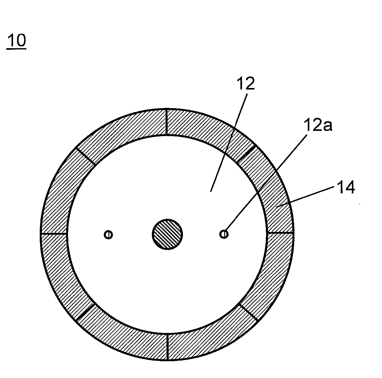
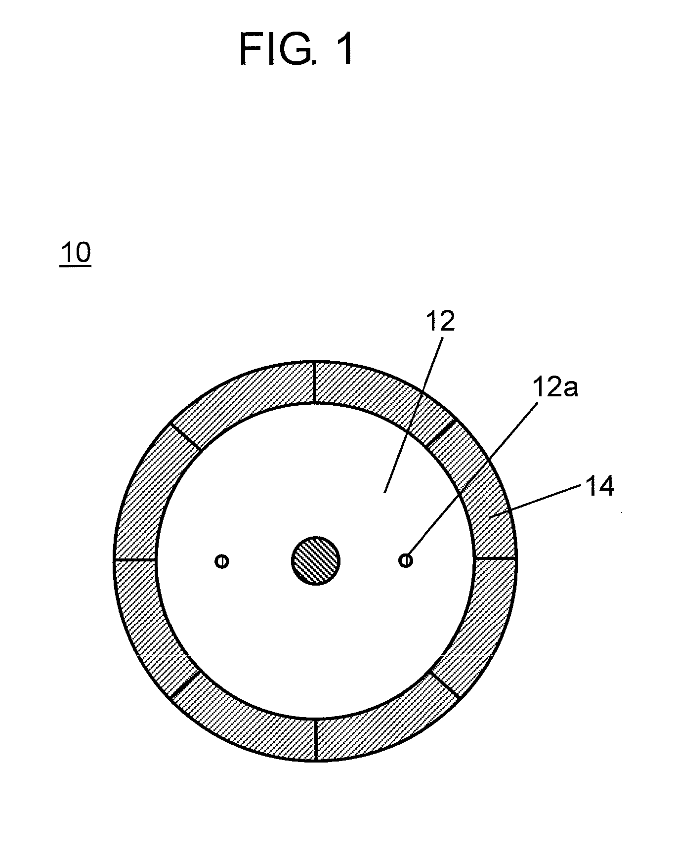
[0030]FIG. 1 is a plan view illustrating an example of the bonded-magnet rotor configured with bonded-magnet formed bodies according to the first exemplary embodiment of the present invention.

[0031]As shown in FIG. 1, bonded-magnet rotor 10 according to the first exemplary embodiment is configured with, for example, bonded-magnet formed bodies 14 with eight poles. The bonded-magnet formed bodies are secured to the outside periphery of the rotor core 12 that is configured with a structure, e.g. laminated silicon steel plates. In this case, each of bonded-magnet formed bodies 14 is chiefly composed of materials, for example, an SmFeN-based magnetic powder and an NdFeB-based magnetic powder that is anisotropic so as to provide an axis of easy magnetization in a uniaxial direction. Each of the bonde...


PUM

PropertyMeasurementUnit
Dimensionaaaaaaaaaa

Abstract

A method of manufacturing a bonded-magnet rotor according to the invention includes forming step and arranging step. The forming step is by forming a bonded-magnet formed body. The arranging step includes: integrating an inside-diameter holding jig, a rotor core, and a rotor-core presser jig; arranging the bonded-magnet formed bodies on the outside periphery of the inside-diameter holding jig; and arranging an outside-diameter-holding magnet-pressure-welding jig to support outside peripheral faces of the bonded-magnet formed bodies. The method further includes steps of: deforming the bonded-magnet formed bodies to fit with the outside peripheral dimension of the rotor core by pressing and transferring the bonded-magnet formed bodies to the rotor core with a forming jig; mutually joining end portions of adjacent ones of the bonded-magnet formed bodies; and integrating the bonded-magnet formed bodies with the rotor core by compressing the bonded-magnet formed bodies. This configuration allows the bonded-magnet rotor with high dimension accuracy.

Description

TECHNICAL FIELD[0001]The present invention relates to a bonded-magnet rotor, a method of manufacturing thereof, and a motor provided therewith.BACKGROUND ART[0002]Permanent magnets configuring a component of a motor are used in a variety of configurations as shown below, in accordance with applications and specifications. The configurations include, for example, a rotor formed with permanent magnets that are secured on the surface of a rotor core thereof, and a rotor formed with permanent magnets of a predetermined shape that are arranged and secured to the inside of a rotor core thereof. With the configurations, the permanent magnets to be secured are selected from a variety of materials, such as sintered magnets and bonded magnets, having different magnetic properties depending on required motor performances. Moreover, the permanent magnets employ various types of shapes, such as circular-arc imbricate magnets, plate-like magnets, and ring magnets.[0003]Moreover, permanent magnets...

Claims


Application Information

Patent Timeline
IPC IPC(8): H02K1/28H02K15/00
CPCH02K1/28H02K15/0012H02K15/03H01F7/021H01F41/0266Y10T29/49012
Inventor ASAI, HIROKI
Owner PANASONIC INTELLECTUAL PROPERTY MANAGEMENT CO LTD
Why Eureka
Try Eureka