Basic function unit of voltage-source converter based on full-controlled devices

Inactive Publication Date: 2013-11-28
CHINA ELECTRIC POWER RES INST +1
View PDF10 Cites 9 Cited by
  • Summary
  • Abstract
  • Description
  • Claims
  • Application Information

AI Technical Summary

Benefits of technology

The present invention provides a new voltage source converter basic function unit that is easy to install and maintain. It is highly modular and insensitive to switch device parameters, resulting in a lower output voltage change rate, smaller dv / dt stress of equipment, and smaller noise. Furthermore, it does not require a filter.

Problems solved by technology

Owing to the switch device turn-off control limits, the valve thyristor is prone to commutation failure, it cannot be used for weak AC system interconnection.
(1) two level voltage source converter adopts pulse width modulation technology, the output voltage of the converter is high frequency jump, which brings about a series of problems like high dv / dt stress of equipment, high system loss, high noise and hardly electromagnetic environment. Even if the three level voltage source converter adopted, it just can alleviate the problem to some extent only.
(2) two level and three level voltage source converter uses switches series technique, because of the switching devices parameters dispersion, each switching device needs to design a complex static voltage balancing circuit, a dynamic voltage balancing circuit and a snubbed circuit, that causes potential problems to the valve during operation. In addition, the switching devices series technique require high performance switches, that needs very high pressing process, it is difficult to manufacture parts, and it is easy to come out assembly defects.
(3) the output voltage waveform of two level and three level voltage source converter has high distortion rate, high harmonic content, so it needs to design the filter circuit to reduce the adverse effects caused by harmonics on the system.

Method used


Image

  • Basic function unit of voltage-source converter based on full-controlled devices
  • Basic function unit of voltage-source converter based on full-controlled devices
  • Basic function unit of voltage-source converter based on full-controlled devices

Examples


Embodiment Construction

[0053]The detail of the embodiments is described as below incorporated with the figures by way of cross-reference for a voltage source converter basic function unit based on full-controlled-devices provided by the present invention.

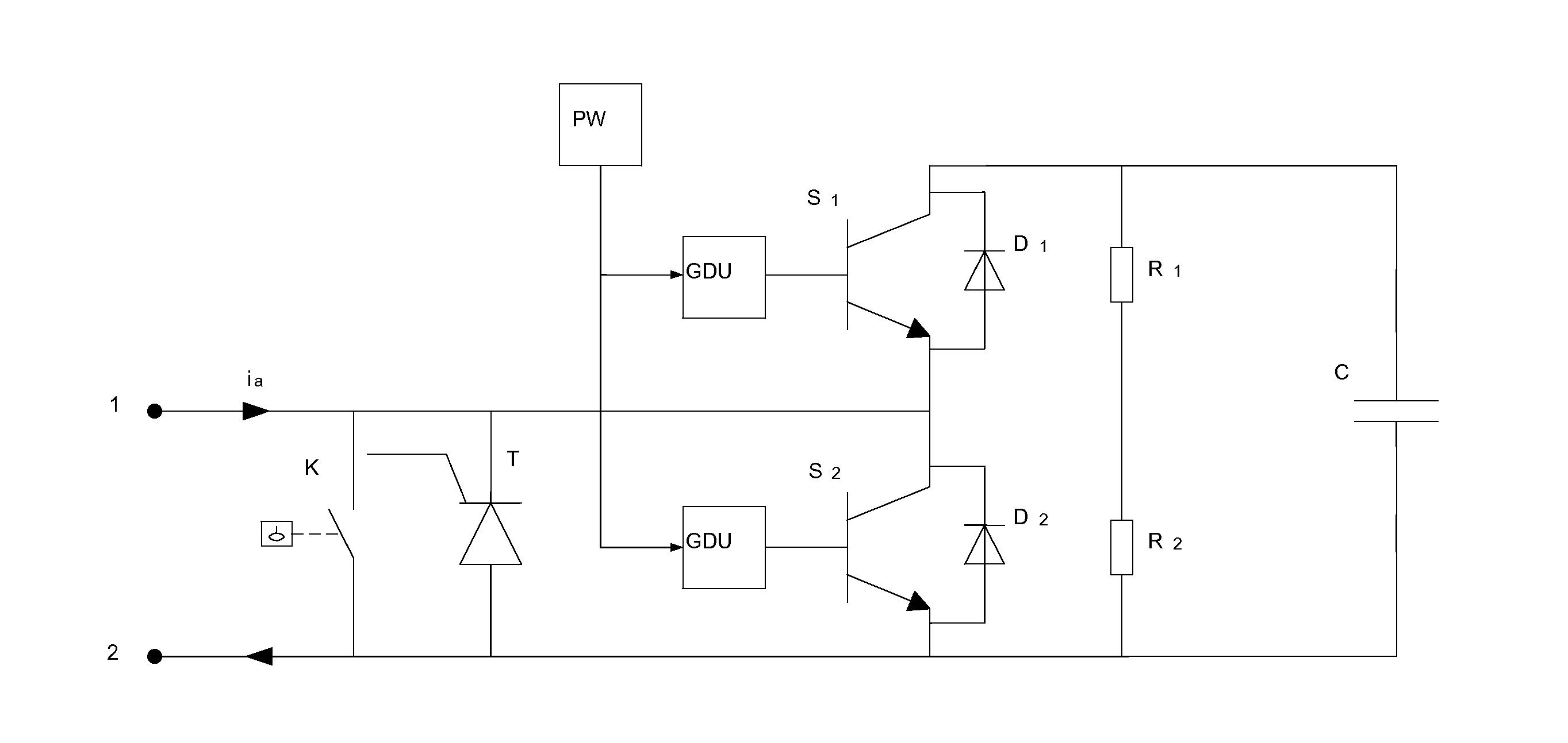
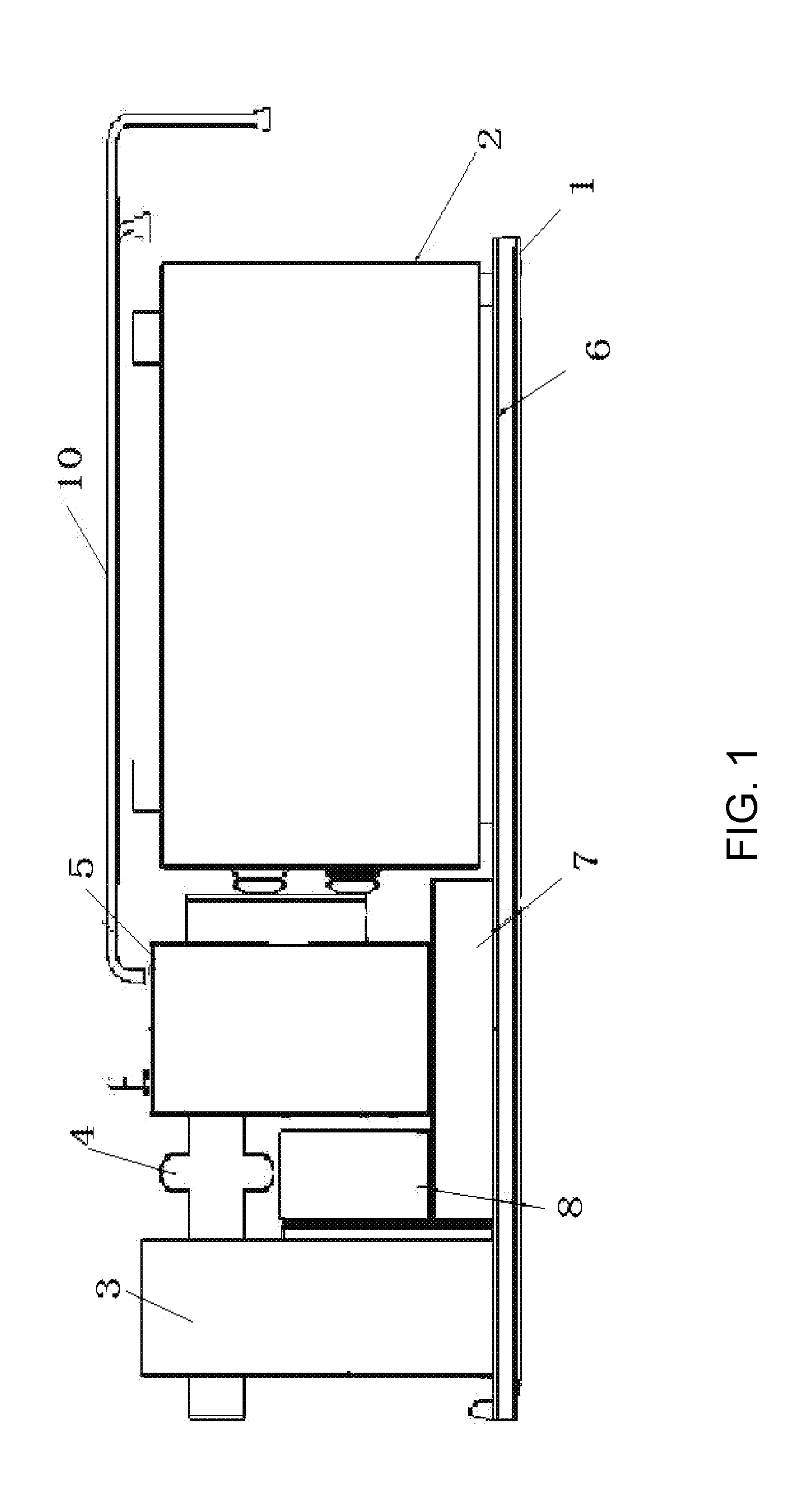
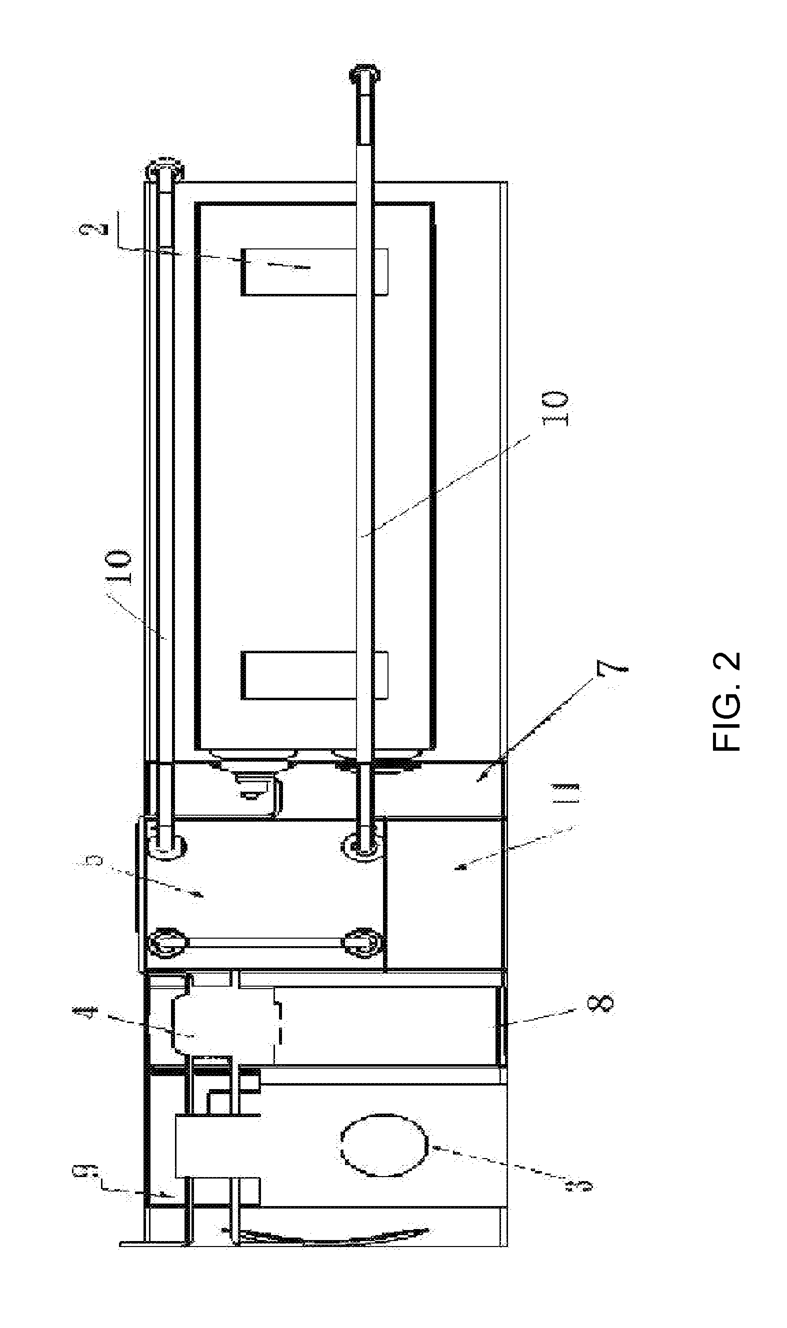
[0054]The voltage source converter basic function unit includes a switching device function module, a by-pass function module, a switch protection function module, a secondary control and protection function module, and a energy storage unit. The secondary control and protection function module, the energy storage unit and the by-pass function module are all fixed on the motherboard 6, there is a slide rail 1 at the bottom of the motherboard 6, the motherboard 6 can move back and forth on the slide rail 1. All equipment of the basic function unit are fixed on the supporting plate, there is a slide rail at the bottom of the plate, it is convenient to maintenance, repair and replace the single basic function unit when the voltage source converter is require...


PUM


Abstract

The present invention relates to a basic function unit of voltage source converter, which is characterized in that the basic function unit includes a switching device function module, a by-pass function module, a switch protection function module, a secondary control and protection function module, and a energy storage unit. The secondary control and protection function module, the energy storage unit and the by-pass function module are all fixed on the motherboard, there is a slide rail at the bottom of the motherboard, the motherboard can move back and forth on the slide rail. The voltage source converter based on that unit is highly modular, insensitive to switch device parameters, lower output voltage change rate, and smaller dv / dt stress of equipment, smaller noise, without filter, convenient installation and maintenance.

Description

RELATED APPLICATIONS[0001]This application is a United States National Stage Application filed under 35 U.S.C 371 of PCT Patent Application Serial No. PCT / CN2011 / 001816, filed Oct. 31, 2011, which claims the benefit of Chinese Patent Application Serial No. 201110030469.6, filed on Jan. 28, 2011, the disclosure of all of which are hereby incorporated by reference in their entirety.FIELD OF THE INVENTION[0002]The invention relates to a power transmission system of AC / DC conversion and power control device based on full-controlled-devices, in particular, it relates to the basic function unit of AC-DC conversion and power control based on IGBT (Insulated Gate Bipolar Transistor) devices applied for DC transmission system.BACKGROUND OF THE INVENTION[0003]With the performance improvement of the power semiconductor switching devices, the power electric devices also developed from widely used half controlled power semiconductor switch, thyristor, to present excellent full controlled devices...

Claims


Application Information

Patent Timeline
IPC IPC(8): H02M1/32
CPCH02M1/32H02M7/003H01L2924/0002H02M7/4835H01L2924/00
Inventor TANG, GUANGFUHE, ZHIYUANLUAN, HONGZHOULI, QIANGLI, YUNPENG
Owner CHINA ELECTRIC POWER RES INST
Why Eureka
Try Eureka