Lighting apparatus

a technology of lighting apparatus and light source, which is applied in the direction of lighting and heating apparatus, semiconductor devices of light sources, coatings, etc., can solve the problems of insufficient improvement of final light output quantity, insufficient use of emitted light, and energy loss, so as to reduce the total configuration amount of lighting apparatus, reduce energy loss, and effectively utilize light emitted

Inactive Publication Date: 2013-11-28
DELTA ELECTRONICS INC
View PDF6 Cites 2 Cited by
  • Summary
  • Abstract
  • Description
  • Claims
  • Application Information

AI Technical Summary

Benefits of technology

The present invention provides a lighting apparatus that effectively uses the light emitted from the LED to increase the light output quantity and brightness. This is achieved through the use of an optical element that partially penetrates and partially reflects the light emitted from the LED. The optical element can be placed inside or outside of the lampshade and can be attached to the outer surface or integrated with the LED. This results in greater energy efficiency and improved brightness, allowing for a decrease in the number of lighting apparatuses needed and reduced cost.

Problems solved by technology

Unfortunately, the optical property of the light-guiding rod 12 will trap the light of the LED 11 inside the light-guiding rod 12 and thus cause some energy loss.
Thus, the emitted light can not be fully used.
Although the reflective surface 121 can reflect the light beam to slightly increase the light output quantity, the energy loss in the light-guiding rod 12 can not be recovered so that the final light output quantity can not be sufficiently improved.
Besides, the light irradiation range of the LED 11 is smaller, so the indoor light brightness may be insufficient.
Moreover, in order to improve the issue of small light irradiation range of the LED 11, which causes the poor indoor light brightness, the amount of the installed lighting apparatuses must be increased.
However, the additional lighting apparatuses will increase the hardware cost, maintaining cost, and energy cost.

Method used


Image

  • Lighting apparatus
  • Lighting apparatus
  • Lighting apparatus

Examples


Embodiment Construction

[0030]The present invention will be apparent from the following detailed description, which proceeds with reference to the accompanying drawings, wherein the same references relate to the same elements.

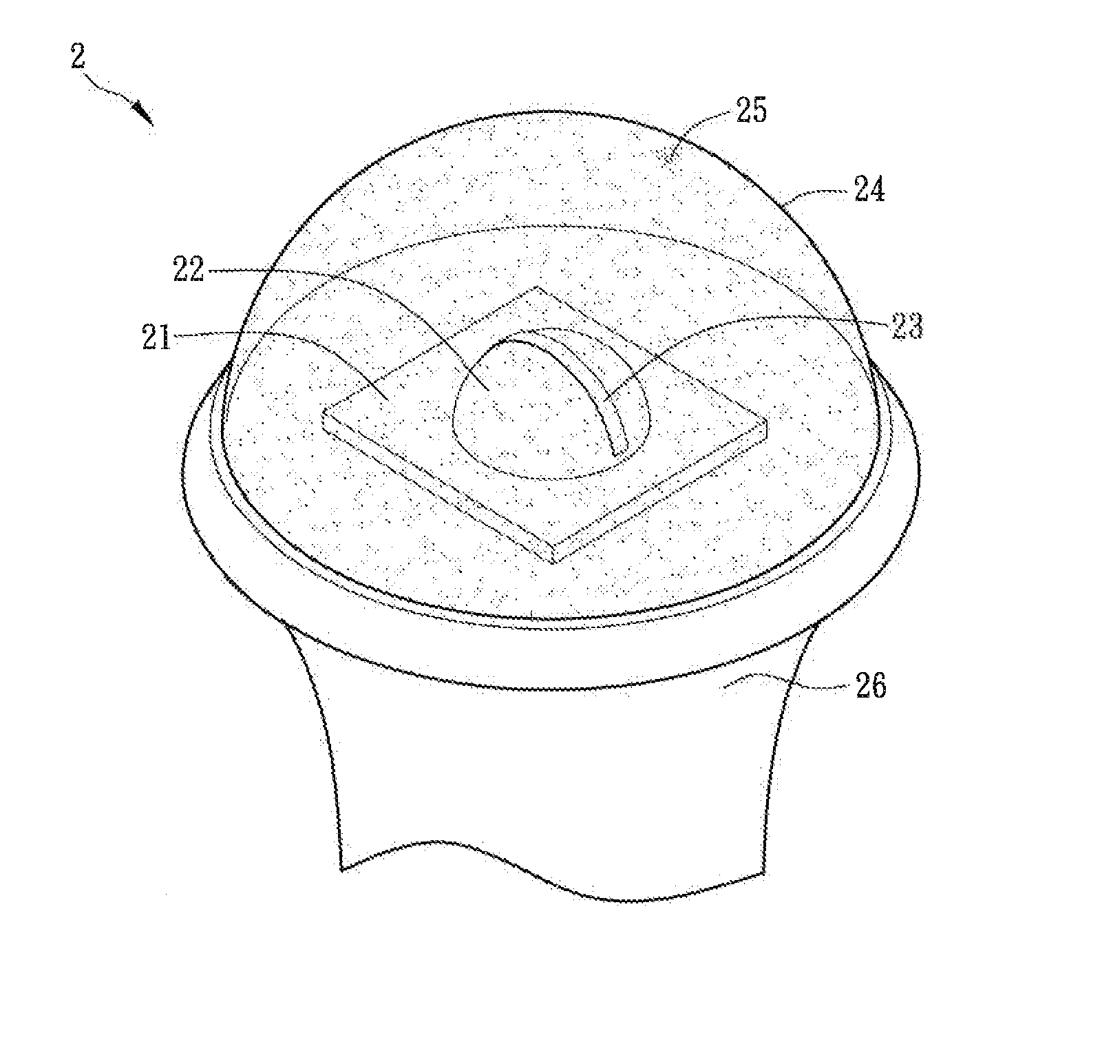
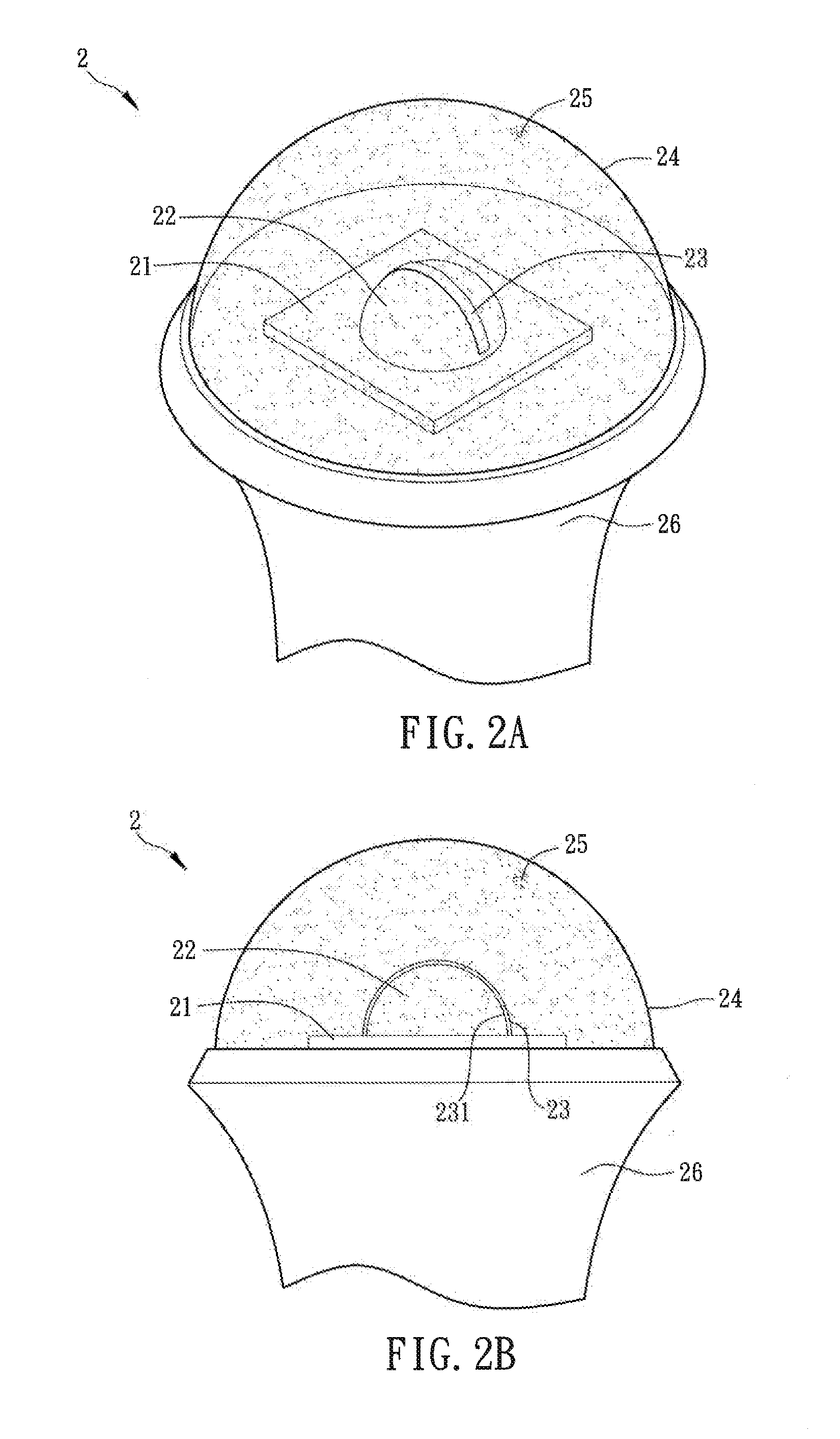
[0031]FIG. 2A is a schematic diagram of a lighting apparatus 2 according to a preferred embodiment of the invention, and FIG. 2B is a sectional view of the lighting apparatus 2. Referring to FIGS. 2A and 2B, the lighting apparatus 2 includes a circuit board 21, at least one LED 22, an optical element 23, a lampshade 24, and at least one fluorescent material 25.

[0032]In this embodiment, only one LED 22 is configured on the circuit board 21, which is for an illustration and is not to limit the present invention. In some embodiments, a plurality of LEDs are configured on the circuit board to increase the lighting illumination of the entire lighting apparatus. In addition, when a plurality of LEDs are configured on the circuit board, the LEDs can emit different color lights. The LEDs can ...


PUM

PropertyMeasurementUnit
Permeabilityaaaaaaaaaa
Fluorescenceaaaaaaaaaa

Abstract

A lighting apparatus includes a circuit board, at least one LED, an optical element, a lampshade and at least one fluorescent material. The LED is disposed on the circuit board. The optical element is disposed above the LED, and has at least one reflective surface so that light emitted from the LED to the optical element partially penetrates through and is partially reflected by the optical element. The lampshade covers the circuit board, the LED and the optical element. The fluorescent material is doped within the lampshade.

Description

CROSS REFERENCE TO RELATED APPLICATIONS[0001]This Non-provisional application claims priority under 35 U.S.C. §119(a) on Patent Application No(s). 101118492 filed in Taiwan, Republic of China on May 24, 2012, the entire contents of which are hereby incorporated by reference.BACKGROUND OF THE INVENTION[0002]1. Field of Invention[0003]The present invention relates to a lighting apparatus and, in particular, to a lighting apparatus with an LED.[0004]2. Related Art[0005]As the progressive of technology, the lighting apparatus has become one of indispensable devices in our life. The lighting apparatus is initially composed of a tungsten bulb but now a light-emitting diode (LED). LED has the advantages of lower power consumption, smaller size and higher brightness.[0006]FIG. 1 is a schematic diagram showing a conventional lighting apparatus. As shown in FIG. 1, the lighting apparatus includes an LED 11 and a light-guiding rod 12 for guiding the light beam along the arrow direction. The li...

Claims


Application Information

Patent Timeline
IPC IPC(8): F21V1/00
CPCF21V1/00F21V3/00F21V13/08F21K9/64F21Y2115/10F21V1/17F21V3/12F21V7/26F21V9/32
Inventor LIAO, WEN-CHIALIN, LI-FANCHEN, SHIH-PENGSHIUE, CHING-CHUAN
Owner DELTA ELECTRONICS INC
Why Eureka
Try Eureka