Current sensor
a current sensor and current technology, applied in the direction of magnetic sensor geometrical arrangement, magnetic field measurement using galvano-magnetic devices, instruments, etc., can solve the problems of reducing the accuracy of measurement, and preventing the reduction of the accuracy with which a current is measured, and reducing the influence of disturbance magnetic fields.
- Summary
- Abstract
- Description
- Claims
- Application Information
AI Technical Summary
Benefits of technology
Problems solved by technology
Method used
Image
Examples
first embodiment
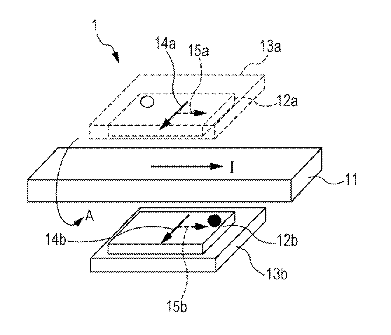
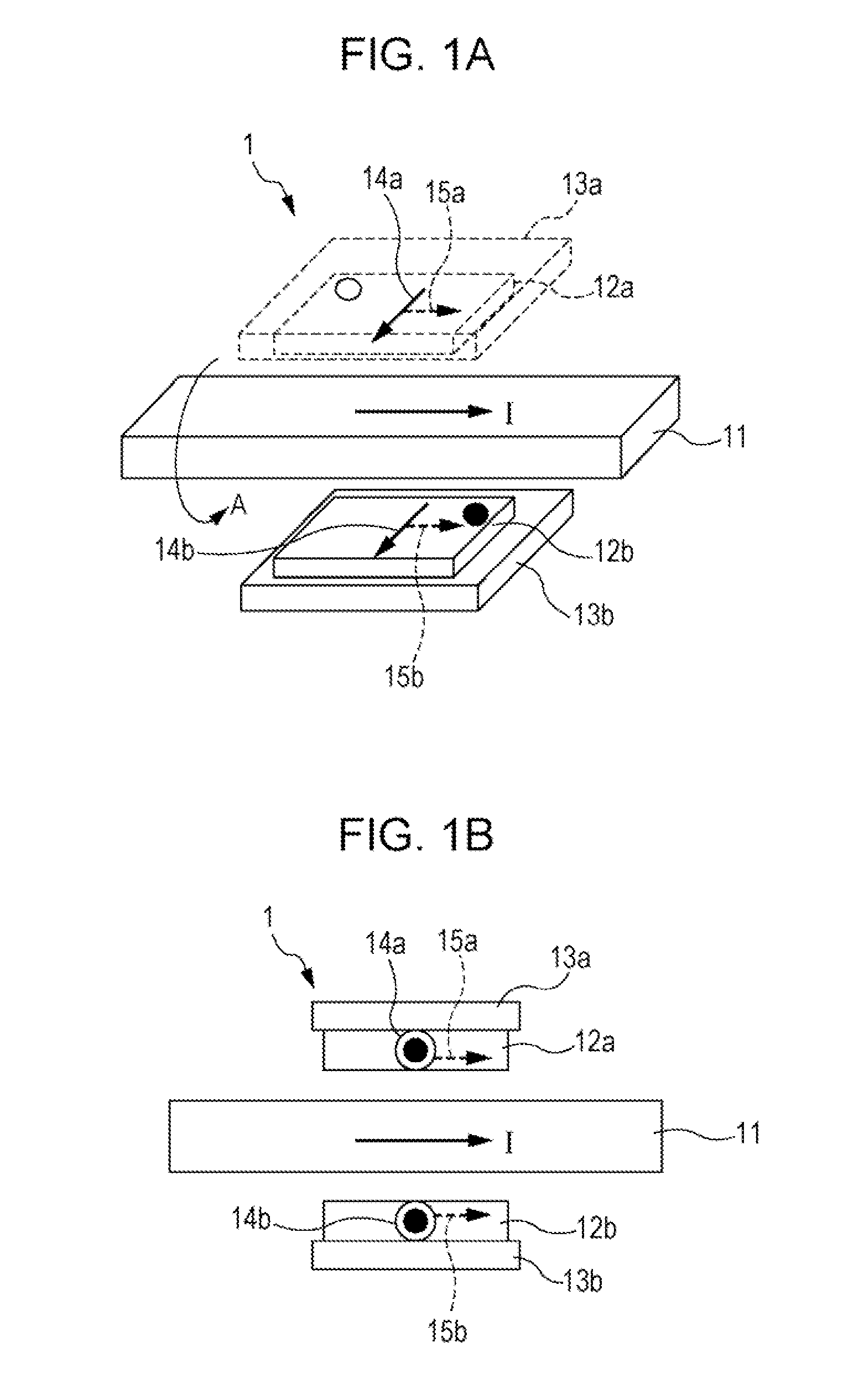
[0050]In a present embodiment, an example of a current sensor 1 according to the present invention will be described. FIGS. 1A and 1B are schematic diagrams illustrating the current sensor 1 according to the present embodiment. FIG. 1A is a perspective view schematically illustrating a configuration of the current sensor 1 and the surroundings thereof, and FIG. 1B is a plan view of the current sensor 1 when the current sensor 1 is viewed from the lower left of the page (the front) in FIG. 1A. Hereinafter, in a perspective view, the lower left of the page is referred to as the front, the upper right of the page is referred to as the rear, the left of the page is referred to as the left, the right of the page is referred to as the right, the top of the page is referred to as the top, and the bottom of the page is referred to as the bottom.
[0051]In FIGS. 1A and 1B, a solid-line arrow placed inside a current line 11 indicates the direction of a current flowing through the current line 1...
second embodiment
[0066]In a present embodiment, another example of the current sensor 1 according to the present invention will be described. FIGS. 5A and 5B are schematic diagrams illustrating a current sensor 1 according to the present embodiment. FIG. 5A is a perspective view schematically illustrating a configuration of the current sensor 1 and the surroundings thereof, and FIG. 5B is a plan view of the current sensor 1 when the current sensor 1 is viewed from the lower left of the page (the front) in FIG. 5A.
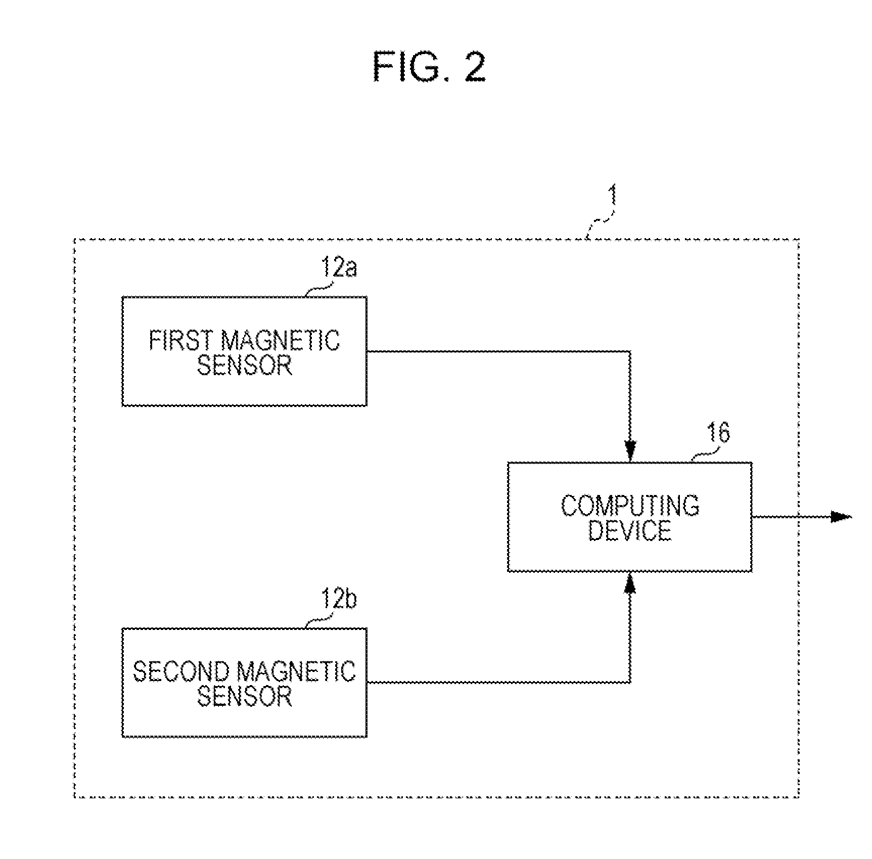
[0067]As illustrated in FIGS. 5A and 5B, the current sensor 1 according to the present embodiment includes a first magnetic sensor 12a and a second magnetic sensor 12b that are placed around a current line 11, and further includes a first circuit board 13a on which the first magnetic sensor 12a is placed, and a second circuit board 13b on which the second magnetic sensor 12b is placed. Moreover, the current sensor 1 further includes a computing device that performs computation using the out...
third embodiment
[0078]In a present embodiment, another example of the current sensor 1 according to the present invention will be described. FIGS. 7A and 7B are schematic diagrams illustrating a current sensor 1 according to the present embodiment. FIG. 7A is a perspective view schematically illustrating a configuration of the current sensor 1 and the surroundings thereof, and FIG. 7B is a plan view of the current sensor 1 when the current sensor 1 is viewed from the lower left of the page (the front) in FIG. 7A.
[0079]As illustrated in FIGS. 7A and 7B, the current sensor 1 according to the present embodiment includes a first magnetic sensor 12a and a second magnetic sensor 12b that are placed around a current line 11, and further includes a first circuit board 13a on which the first magnetic sensor 12a is placed, and a second circuit board 13b on which the second magnetic sensor 12b is placed. Moreover, the current sensor 1 further includes a computing device that performs computation using the out...
PUM
 Abstract
Description
Claims
Application Information
 - R&D
- Intellectual Property
- Life Sciences
- Materials
- Tech Scout
- Unparalleled Data Quality
- Higher Quality Content
- 60% Fewer Hallucinations
Browse by: Latest US Patents, China's latest patents, Technical Efficacy Thesaurus, Application Domain, Technology Topic, Popular Technical Reports.
© 2025 PatSnap. All rights reserved.Legal|Privacy policy|Modern Slavery Act Transparency Statement|Sitemap|About US| Contact US: help@patsnap.com


