Eureka AIR delivers breakthrough ideas for toughest innovation challenges, trusted by R&D personnel around the world.

Hybrid plasma reactor

a plasma reactor and hybrid technology, applied in the field of plasma reactors, can solve the problems of insufficient response of the reactor using one of the transformer coupled plasma sources and the inductively coupled plasma sources to the demands, the difficulty of igniting plasma or maintaining the ignited plasma in a low-pressure atmosphere, and the inability to adequately respond to the demands of the reactor. achieve the effect of generating a large volume of plasma and wide operation area

Active Publication Date: 2013-11-21
NEW POWER PLASMA CO LTD
View PDF12 Cites 16 Cited by
  • Summary
  • Abstract
  • Description
  • Claims
  • Application Information

AI Technical Summary

Benefits of technology

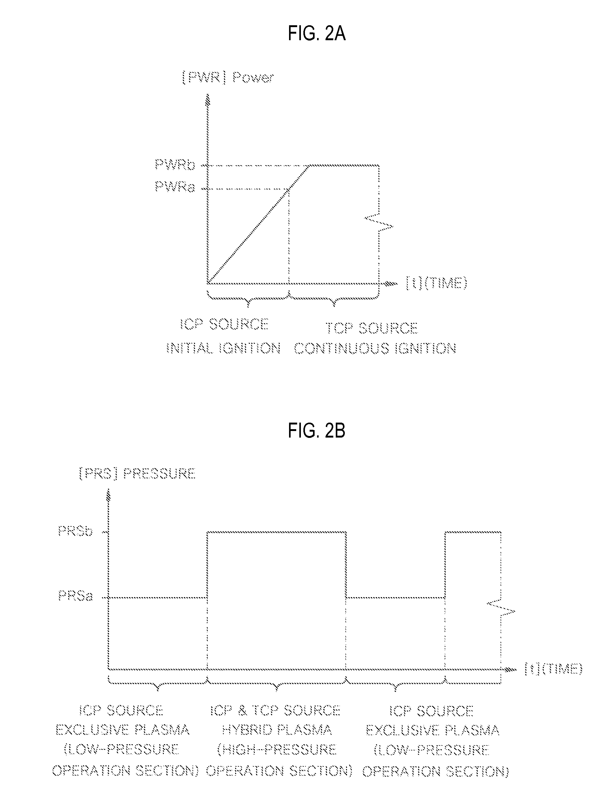
The hybrid plasma reactor described in this patent has the ability to generate plasma in a wide range of pressure areas using both an inductively coupled plasma source and a transformer coupled plasma source. It can easily maintain plasma ignition in low pressure areas and produce a large amount of plasma without damaging the reactor in high pressure areas. The reactor can also operate effectively with a single power supply and selectively drive either the inductively coupled plasma source or the transformer coupled plasma source, or in a combination of the two.

Problems solved by technology

Since the remote plasma reactor having the transformer coupled plasma source is operated in a relatively high-pressure atmosphere according to a characteristic thereof, it is difficult to ignite plasma or maintain the ignited plasma in a low-pressure atmosphere.
The remote plasma reactor having the inductively coupled plasma source can be operated in a relatively low-pressure atmosphere according to a characteristic thereof, but supplied power should be increased such that remote plasma reactor having the inductively coupled plasma source can be operated in a high-pressure atmosphere, so in this case, the inside of the reactor body may be damaged due to ion bombardment.
However, the conventional remote plasma reactor employing one of the transformer coupled plasma source and the inductively coupled plasma source failed to appropriately respond to the demands.

Method used


Image

  • Hybrid plasma reactor
  • Hybrid plasma reactor
  • Hybrid plasma reactor

Examples


Embodiment Construction

[0060]Hereinafter, an exemplary embodiment of the present invention will be described in detail with reference to the accompanying drawings for the full understanding of the present invention. The embodiment of the present invention will be modified into various forms and it shall not be construed that the scope of the present invention is limited to the embodiment to be described below. The embodiment of the present invention is provided to more fully explain the present invention to a skilled person in the art. Accordingly, a shape, or the like of an element in the drawing may be exaggerated for more accurate description. Like reference numerals indicate like elements throughout the specification and drawings. In the following description, detailed explanation of known related functions and constitutions may be omitted to avoid unnecessarily obscuring the subject manner of the present invention.

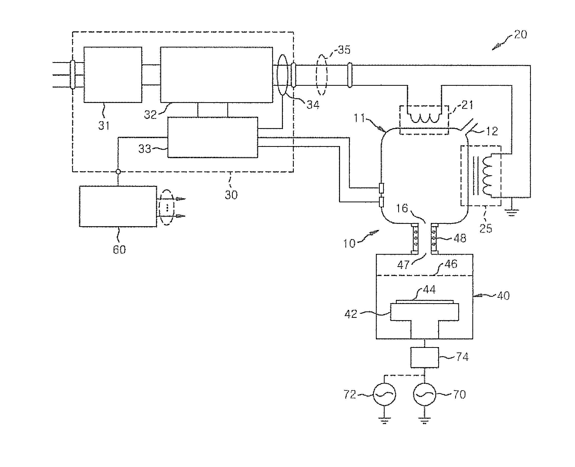
[0061]FIG. 1 is a block diagram illustrating a general construction of a hybrid plasma ...


PUM


Abstract

A hybrid plasma reactor includes a reactor body having a plasma discharge space, a gas inlet, and a gas outlet; a hybrid plasma source including an inductive antenna inductively coupled to plasma formed in the plasma discharge space and a primary winding coil transformer coupled to the plasma and wound in a magnetic core; and an alternating switching power supply for supplying plasma generation power to the inductive antenna and the primary winding coil. The hybrid plasma reactor induces a plasma discharge using the inductively coupled plasma source and the transformer coupled plasma source, so that it has a wide operational area from a low pressure area to a high pressure area.

Description

CROSS-REFERENCE TO RELATED APPLICATION[0001]This application claims priority of Korean patent application numbers 10-2011-0116138 filed on Nov. 9, 2011, Korean patent application number 10-2011-0117240 filed on Nov. 10, 2011, Korean patent application number 10-2011-0143294 filed on Dec. 27, 2011, and Korean patent application number 10-2011-0143302 filed on Dec. 27, 2011. The disclosure of each of the foregoing applications is incorporated herein by reference in its entirety.BACKGROUND[0002]1. Technical Field[0003]The present invention relates to a plasma reactor for generating activated gas containing ions, free-radical, atoms, and molecules by a plasma discharge and performing a plasma processing for a solid, powder, gas, etc. with the activated gas, and more particularly to a hybrid plasma reactor for complexly generating plasma by using an inductively coupled plasma source and a transformer coupled plasma source.[0004]2. Background Art[0005]A plasma discharge has been used for ...

Claims


Application Information

Patent Timeline
Patent Type & Authority Applications(United States)
IPC IPC(8): H01J37/32
CPCH01J37/32816H01J37/321
Inventor CHOI, DAE-KYU
Owner NEW POWER PLASMA CO LTD
Why Eureka
Eureka Blog
Learn More