Weld Stress Compensation System

Active Publication Date: 2013-11-14
MERIDIAN STAINLESS
View PDF14 Cites 5 Cited by
  • Summary
  • Abstract
  • Description
  • Claims
  • Application Information

AI Technical Summary

Benefits of technology

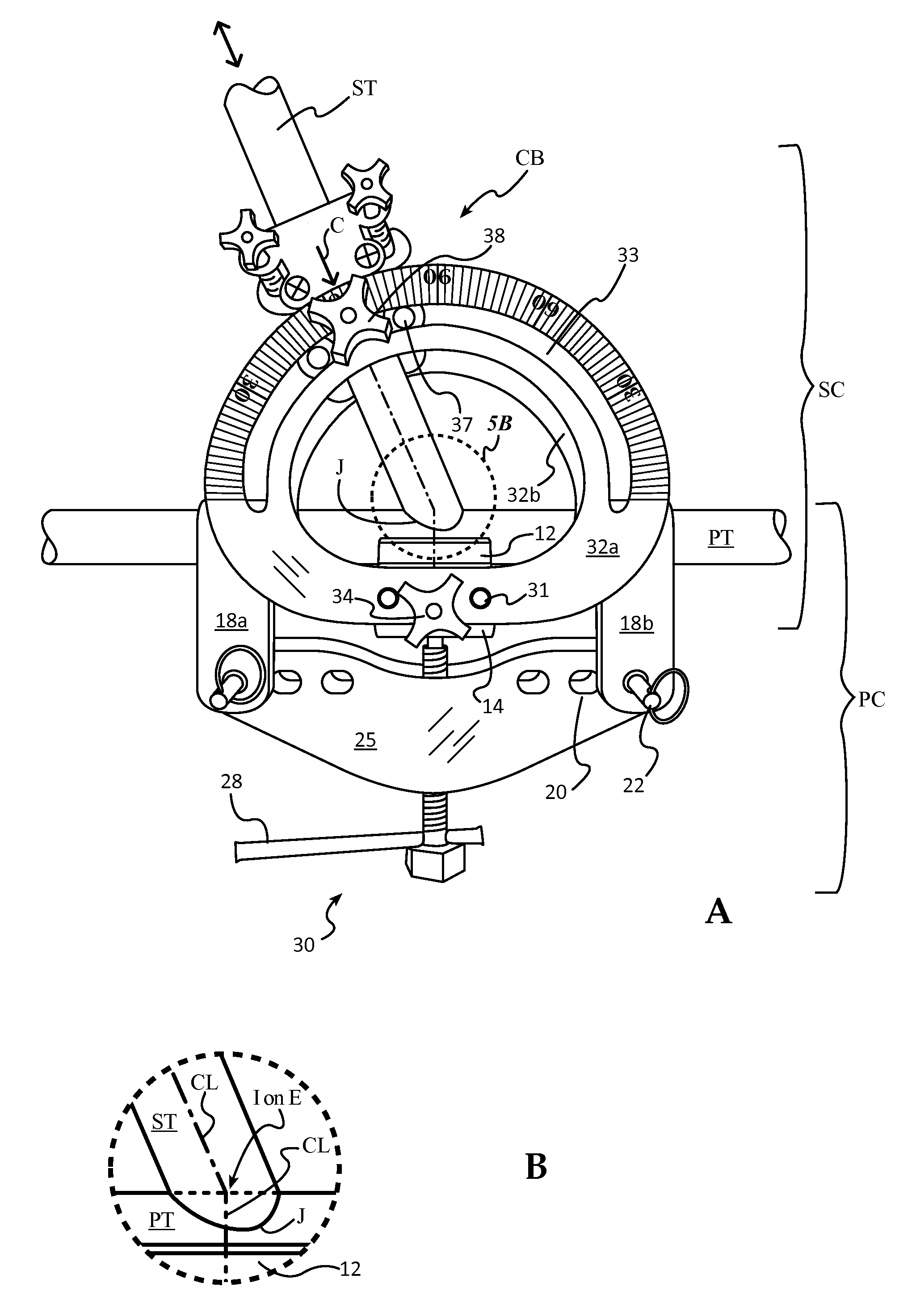
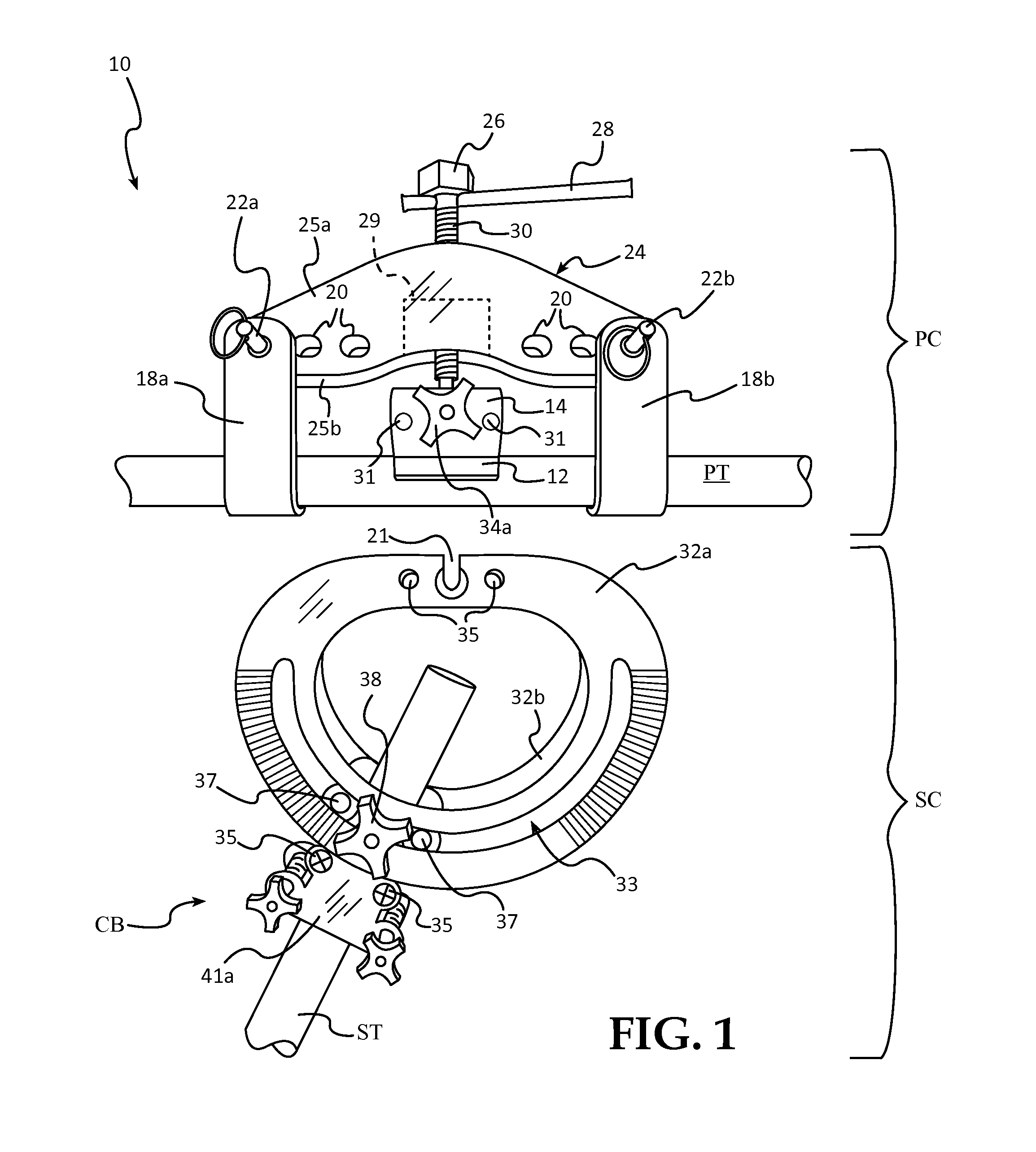
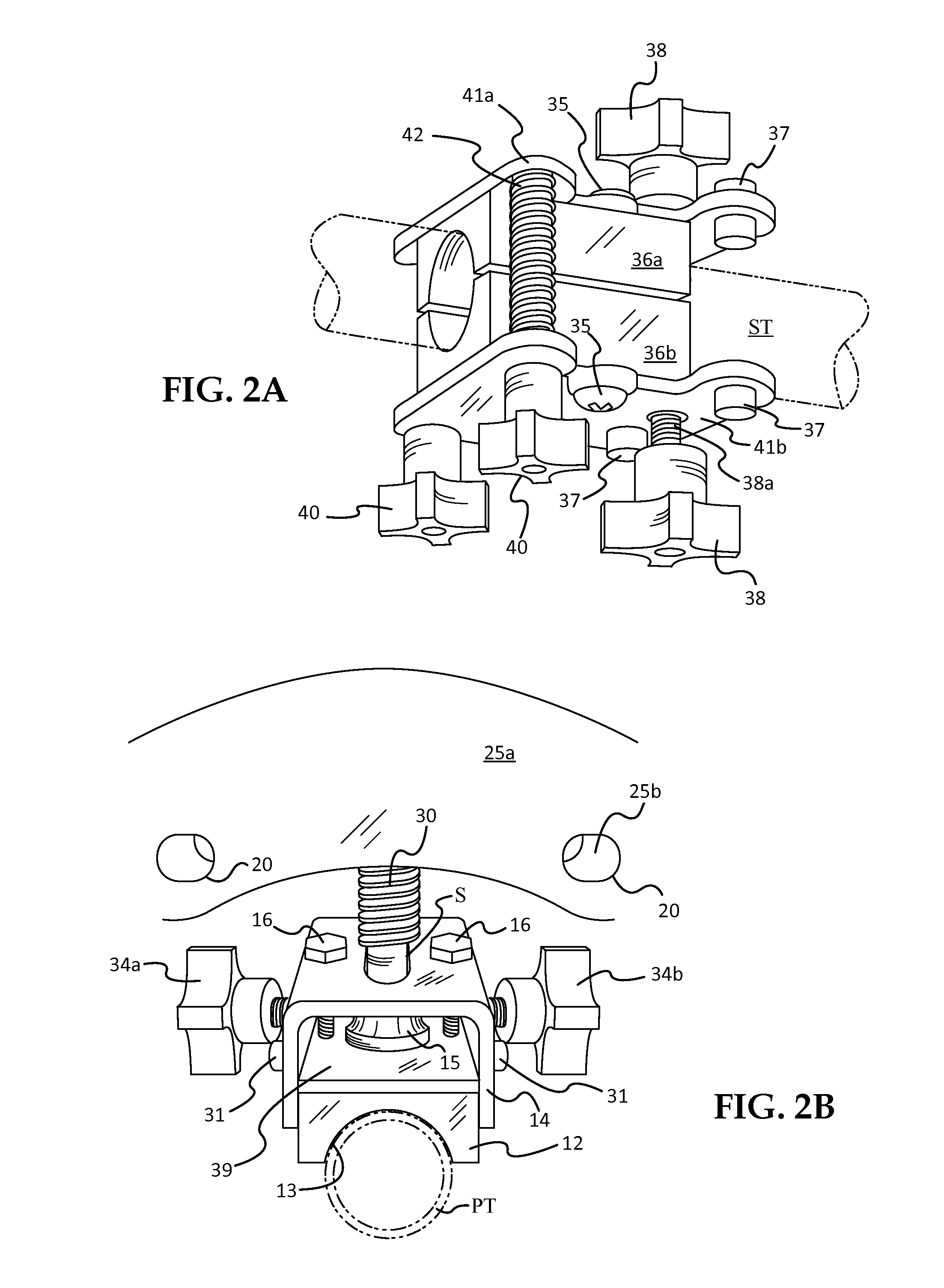
This patent is about a method for welding spindles onto a boat railing using a clamp assembly and a tubular saw. The method includes using a primary clamp to hold a spindle in place while it is welded onto a rail. A secondary clamp is then used to hold the spindle in proper orientation for the entire rail. This allows for precise placement of the spindle before welding. The clamps are made of metal to help control warping, and the method allows for faster and more precise welding of complex and compound curved tubular fabrications. The invention also includes a saddle cutting fixture for accurately fitting spindles onto a deck plate. Overall, this patent provides a faster and more precise way to weld spindles onto boat railings.

Problems solved by technology

Welding of round tubular parts to each other is particularly difficult as at least one of the tubes must be cut in a compound, 3-dimensional curve in order to engage a second round tube for welding.
Where the saddle cut is not sufficiently precise, a gap is presented at the join position which is, at best, difficult to fill properly in order to make a sound, strong weld.
A similar problem exists where a round tube must be welded to a flat surface at an angle, requiring a precise miter cut.
This problem is compounded by the fact that at the point of welding join of the two tubes, the primary tube will bend due to the stresses produced during welding.
This bend not only results in the included join angle between the two tubes being incorrect, but also an unsightly bow is produced in the primary tube.
In some cases the amount of warping of the horizontal rail occurring at every join of the stanchions is sufficient to present an objectionable wavy appearance.
The current practice of positioning of the parts with blocks in preparation for welding them together fails to provide any warp-compensation.
However, this process is inherently inaccurate due to the various sizes of tubing used.
The result is experience-based guesswork that often results in do-overs and wasted material.
Where the horizontal rail run is long, to have even only the last stanchion weld position warp, often results in rejecting the entire rail.
This results in requiring remaking the entire rail, a substantial waste of time and material, and results in a substantial, two or three-fold increase of the rail assembly expense.
This makes the assembly highly labor intensive; the work proceeds slowly, one spindle at a time.

Method used


Image

  • Weld Stress Compensation System
  • Weld Stress Compensation System
  • Weld Stress Compensation System

Examples


Embodiment Construction

[0034]The following detailed description illustrates the invention by way of example, not by way of limitation of the scope, equivalents or principles of the invention. This description will clearly enable one skilled in the art to make and use the invention, and describes several embodiments, adaptations, variations, alternatives and uses of the invention, including what is presently believed to be exemplary modes of carrying out the invention.

[0035]In this regard, the invention is illustrated in the several figures, and is of sufficient complexity that the many parts, interrelationships, and sub-combinations thereof simply cannot be fully illustrated in a single patent-type drawing. For clarity and conciseness, several of the drawings show in schematic, or omit, parts that are not essential in that drawing to a description of a particular feature, aspect or principle of the invention being disclosed. Thus, the best mode embodiment of one feature may be shown in one drawing, and th...


PUM

PropertyMeasurementUnit
Pressureaaaaaaaaaa
Angleaaaaaaaaaa
Radiusaaaaaaaaaa

Abstract

Weld stress compensation system and method comprising: 1) a primary tube / rod clamp; 2) a secondary tube / rod clamp for selectively and accurately, angularly positioning the secondary tube relative to the primary tube. The secondary clamp is transferable while a secondary tube / rod is clamped therein to: 3) a saddle cutting fixture to produce a concave, relieved portion in the end of the secondary tube / rod with flanking flanges that fit precisely over the primary tube at the join intersection; 4) a miter-cut fixture for miter cutting of tube / rod ends to fit flat surfaces or conversely-cut tubes / rods for angular joins; and 5) a welding fixture for precise angular positioning of a miter cut tube / rod to a deck, wall, or stair plate. The primary clamp includes an adjustable pressure pad that applies pressure to the side of the primary tube opposite the secondary tube weld join line thereby preventing warping due to weld stresses.

Description

CROSS-REFERENCE TO RELATED CASE[0001]This is the US Regular application corresponding to its priority documents, Provisional Application Ser. No. 61 / 646,445, filed May 14, 2012 by the same inventor under the same title, the date of which is claimed for priority under 35 USC §120 ff.FIELD[0002]This invention relates to a weld stress compensation system and more particularly an apparatus and method for compensation of stress and warping in tubular and rod members generated during welding of such members to each other. The inventive system is implemented in a multi-part fixture assembly for accurately cutting tubular parts and for holding the parts in proper angular position during welding so that the tubes do not become warped, deformed or skewed. The inventive system is particularly useful for welding of stainless steel or aluminum tubing used in marine applications, such as railings, stanchions, platforms, ladders, stairways and other fittings.BACKGROUND[0003]Welding of round tubula...

Claims


Application Information

Patent Timeline
IPC IPC(8): B23K37/053
CPCB23K37/0533B23K37/053B25B5/003B25B5/006B25B5/147B25B5/163
Inventor UECKER, TIMOTHY M.
Owner MERIDIAN STAINLESS
Why Eureka
Try Eureka