
Gas showerhead, method for making the same and thin film growth reactor

a technology of gas showerhead and reactor, which is applied in the direction of machines/engines, water supply installations, drawing-off water installations, etc., can solve the problems of complex design, insufficient uniformity of gas entering the reaction chamber, and complex design, so as to improve the qualified rate of workpieces, reduce the difficulty of manufacture, and improve the effect of the utilization efficiency of reactant gas

Active Publication Date: 2013-11-14
ADVANCED MICRO FAB EQUIP INC CHINA
View PDF21 Cites 63 Cited by
  • Summary
  • Abstract
  • Description
  • Claims
  • Application Information

AI Technical Summary

Benefits of technology

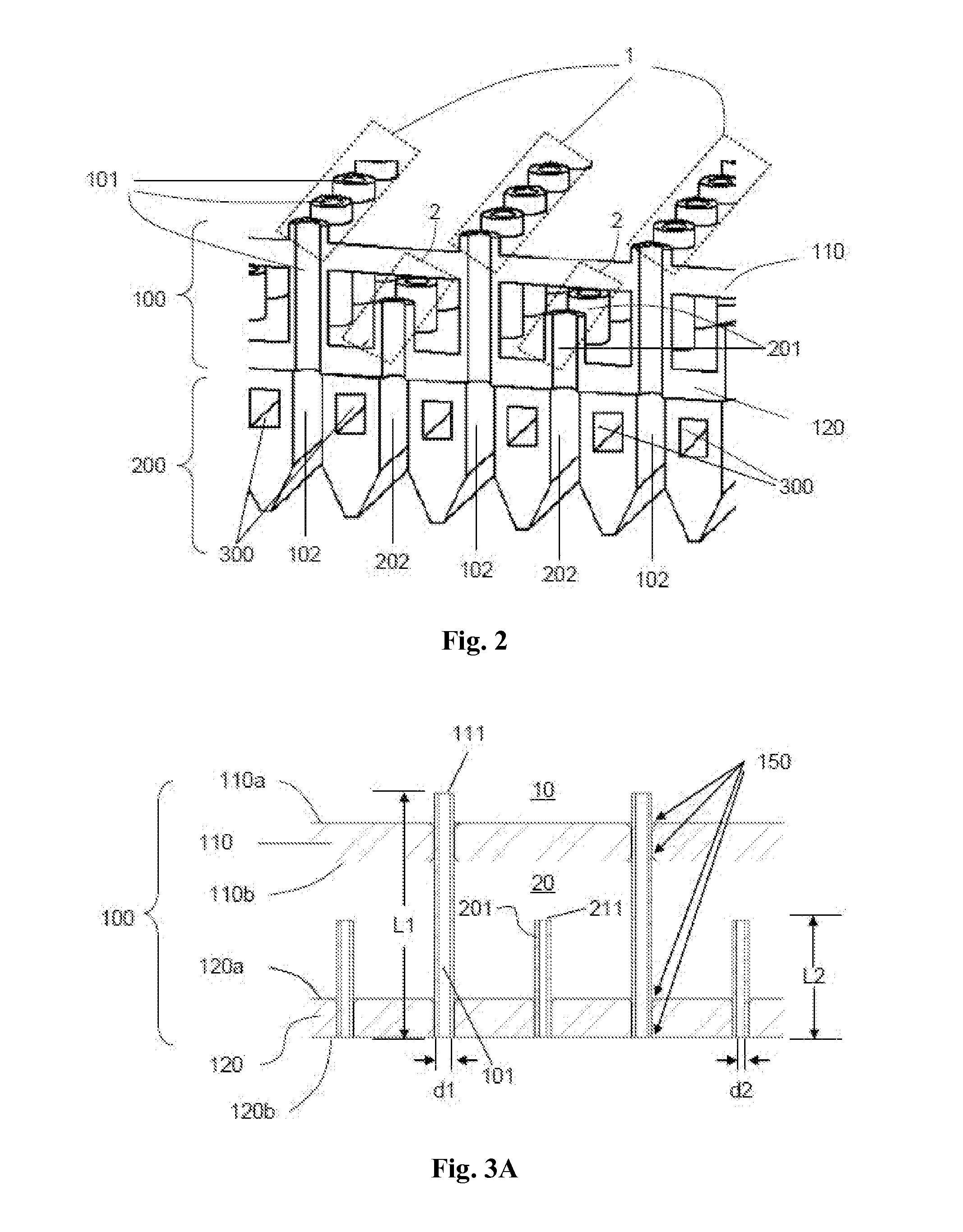
The gas showerhead has two parts, a gas distribution and diffusion plate and a water cooling plate, that are assembled together in a detachable mechanical way. This makes the manufacturing process simple and allows for easy cleaning of the two parts separately. The gas distribution and diffusion plate is placed above the water cooling plate, which helps to distribute the gas evenly and improves the utilization efficiency of the gas and the quality of processing. The two parts are made separately, making the manufacturing process easier, while preventing leakage of the cooling liquid. The gas distribution and diffusion plate and the water cooling plate can also be cleaned or replaced independently, reducing costs and improving efficiency.

Problems solved by technology

However, in the prior art, those devices have complex designs, and the gas entering the reaction chamber does not have sufficient uniformity.
Furthermore, the cooling system must be capable of preventing the rising of the temperature effectively so as to prevent any leakages, which results in the complex design and increased manufacturing cost of the showerhead.

Method used


Image

  • Gas showerhead, method for making the same and thin film growth reactor
  • Gas showerhead, method for making the same and thin film growth reactor
  • Gas showerhead, method for making the same and thin film growth reactor

Examples


Embodiment Construction

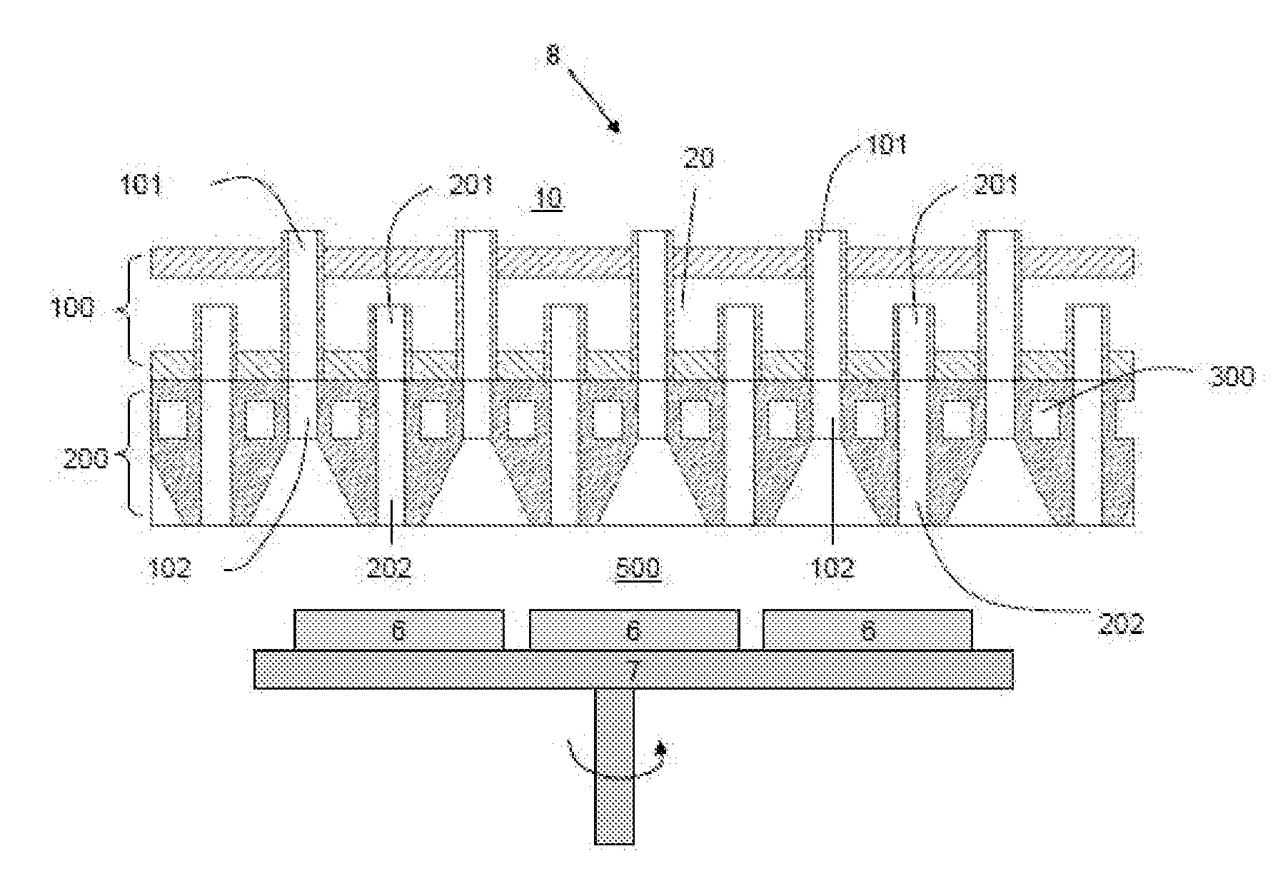
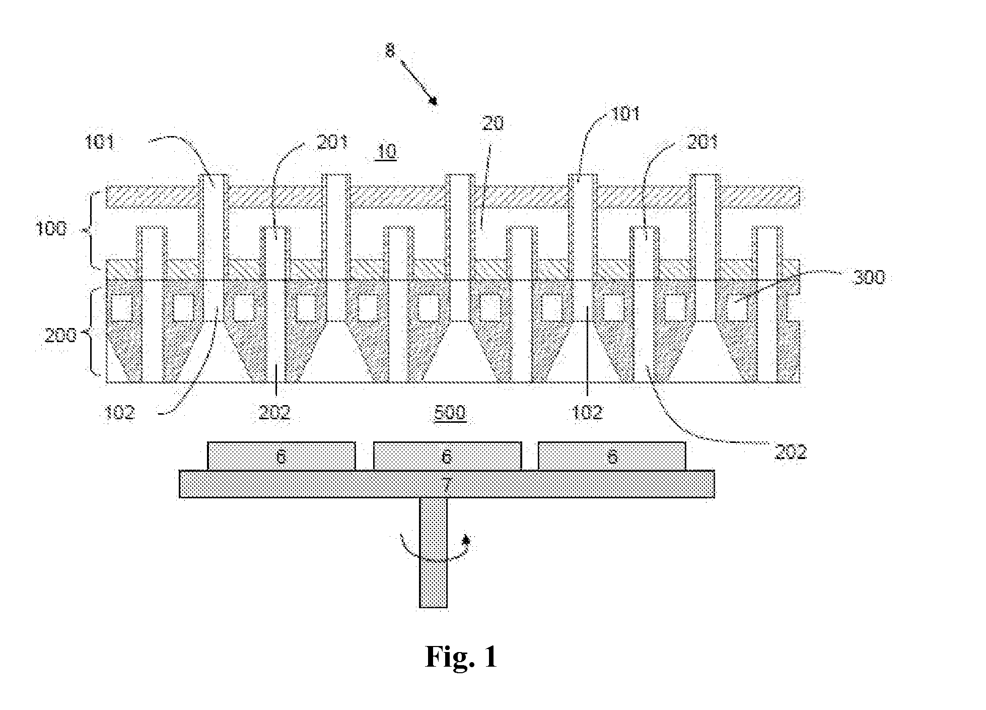
[0060]FIG. 1 is a schematic view showing the structure of a thin film growth reactor according to the present application. As shown in FIG. 1, the present application provides a thin film growth reactor including a reaction chamber 8. A supporting member 7 and workpieces 6 to be processed provided on the supporting member 7 are arranged in the reaction chamber 8. The supporting member 7 is rotatable in a substantially horizontal direction, and a gas showerhead is arranged above the supporting member 7 so as to isolatedly distribute and diffuse various reactant gases into a reaction zone 500 to be mixed uniformly. The gas showerhead includes a gas distribution and diffusion plate 100 and a water cooling plate 200 located below the gas distribution and diffusion plate. The gas distribution and diffusion plate 100 and the water cooling plate 200 are two separated components which may be assembled integrally in a detachable mechanical manner and may be disassembled for cleaning or repla...


PUM

PropertyMeasurementUnit
lengthaaaaaaaaaa
lengthaaaaaaaaaa
inner diameteraaaaaaaaaa

Abstract

The present application provides a gas showerhead including a gas distribution and diffusion plate and a water cooling plate, the gas distribution and diffusion plate includes several columns of first gas diffusion passages connecting to a first reactant gas source and several columns of second gas diffusion passages connecting to a second reactant gas source; the water cooling plate having cooling liquid passages is arranged below the gas distribution and diffusion plate, and the water cooling plate is provided with first gas outlet passages provided for the reactant gas in the first gas diffusion passages to flow out and second gas outlet passages provided for the reactant gas in the second gas diffusion passages to flow out, so as to isolatedly feed at least two reactant gases into a reaction chamber.

Description

[0001]The present application claims the benefit of Chinese Patent Application No. 201210147710.8 titled “GAS SHOWERHEAD, METHOD FOR MAKING THE SAME AND THIN FILM GROWTH REACTOR” and filed with the Chinese State Intellectual Property Office on May 11, 2012, the entire disclosure of which is incorporated herein by reference.FIELD OF THE INVENTION[0002]The present application relates to the technical field of feeding gas into a reaction chamber, in particular to a device for uniformly feeding reactant gases into a reaction chamber to be mixed.BACKGROUND OF THE INVENTION[0003]Currently, various reaction chambers have been used in making semiconductor devices, flat plate cell and solar cell or the like, for example, Chemical Vapor Deposition (CVD), Plasma Enhanced Chemical Vapor Deposition (PECVD), Metal Organic Chemical Vapor Deposition (MOCVD), Vapor Phase Epitaxy growth (VPE). In practical application, the flow velocity of the reactant gases entering in the reaction chamber can not b...

Claims


Application Information

Patent Timeline
Patent Type & Authority Applications(United States)
IPC IPC(8): F16L53/00
CPCF16L53/00H01L21/67109C23C16/45565C23C16/45572C23C16/45574Y10T137/6416Y10T137/0402H01L21/0262C23C16/45517C23C16/45578C23C16/45514C30B25/14
Inventor JIANG, YONGZHOU, NINGHO, HENRYDU, ZHIYOU
Owner ADVANCED MICRO FAB EQUIP INC CHINA
Learn More