
METHOD OF OPERATING AN INTERNAL COMBUSTION ENGINE WITH DIRECT FUEL INJECTION AND LOW NOx EMISSIONS

a technology of internal combustion engine and direct fuel injection, applied in the direction of electrical control, process and machine control, etc., can solve the problems of reduced flexibility, poor dynamic response of vehicles, limited useful application of rzv operating mode in higher engine load ranges, etc., and achieve the effect of stably implemented

Inactive Publication Date: 2013-11-07
DAIMLER AG
View PDF4 Cites 9 Cited by
  • Summary
  • Abstract
  • Description
  • Claims
  • Application Information

AI Technical Summary

Benefits of technology

The patent text discusses the use of downsizing in automotive engineering to reduce CO2 emissions. Downsizing involves constructing and operating small-displacement engines that offer similar or better driving behavior as their larger predecessors. This results in lower fuel consumption and reduced CO2 emissions. Partial operating modes with controlled auto-ignition (RZV) exhibit lower fuel consumption and reduced NOx emissions when compared to stoichiometric Otto-cycle combustion systems. Additionally, the NAV combustion method improves engine smoothness and allows for extended operating range.

Problems solved by technology

Smaller displacement engines are, however, characterized by having lower torque, especially at low speeds, leading to the vehicle having a poorer dynamic response and thus reduced flexibility.
This low-emission, efficient RZV operating mode with controlled auto-ignition can, however, only be used at a lower and possibly medium engine load / engine speed range, as knocking tendency increases with decreasing charge dilution, and thus the useful application of the RZV operating mode in higher engine load ranges is limited.
Although the region of the engine characteristics map for the respective partial operating mode can be expanded by using water injection, the operating range of a pure RZV partial operating mode is nevertheless limited despite water injection.

Method used


Image

  • METHOD OF OPERATING AN INTERNAL COMBUSTION ENGINE WITH DIRECT FUEL INJECTION AND LOW NOx EMISSIONS
  • METHOD OF OPERATING AN INTERNAL COMBUSTION ENGINE WITH DIRECT FUEL INJECTION AND LOW NOx EMISSIONS

Examples


Embodiment Construction

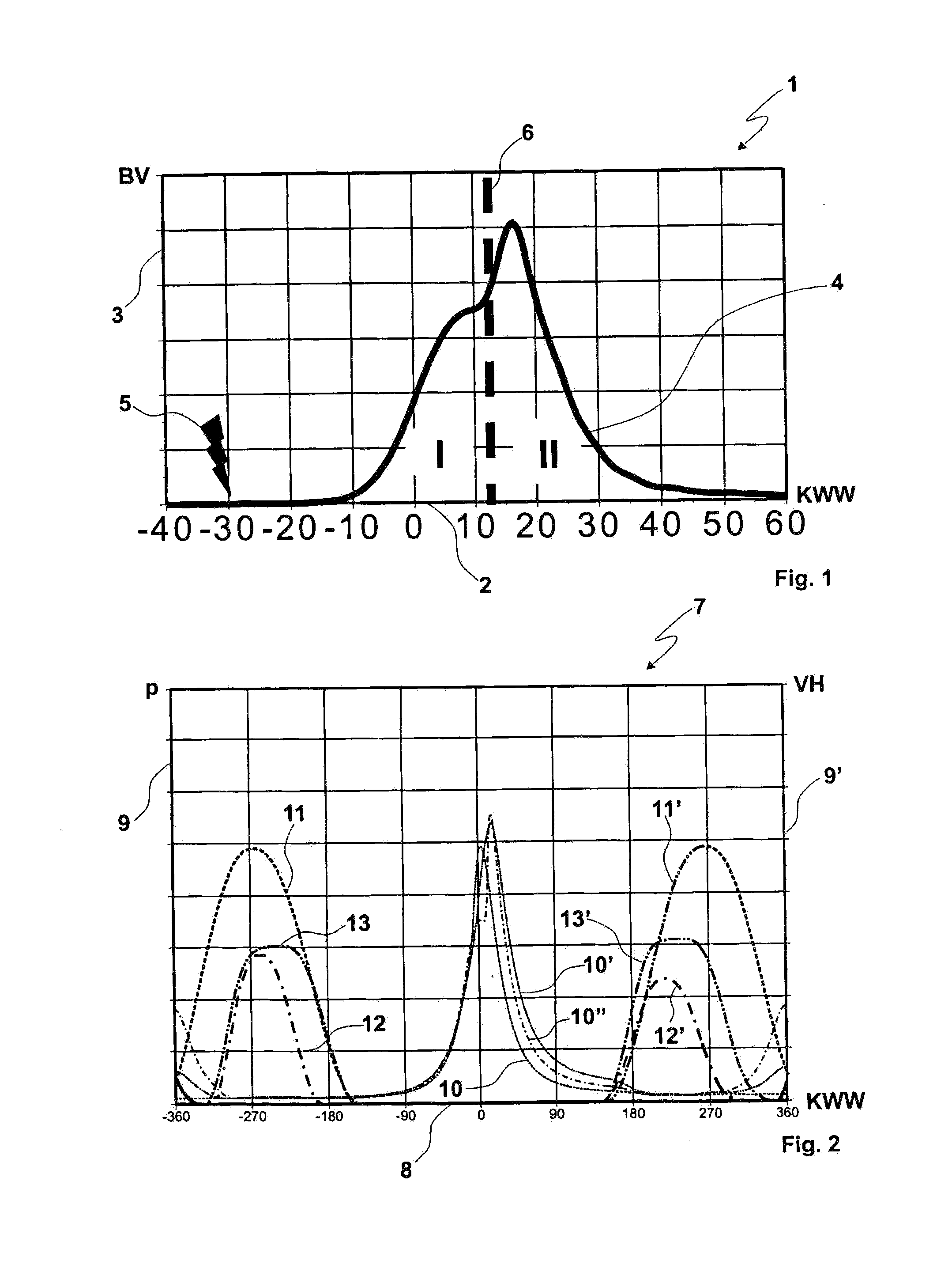
[0049]FIG. 1 shows a combustion curve diagram 1 of a NAV partial operating mode, where the crank angle CA is plotted along the X-axis 2 in degrees and where a combustion development is plotted up the Y-axis 3 in Joules. The combustion development of the NAV partial operating mode is represented by a curve 4. A fuel / exhaust gas / air mixture introduced into the respective combustion chamber is spark ignited at an ignition point 5 and at a crank angle of −30°+ / −5° CA. Up to a boundary line 6 the fuel / exhaust gas / air mixture introduced into the respective combustion chamber burns with a Otto-cycle flame front combustion (FFV). From boundary line 6, the fuel / exhaust gas / air mixture, having become further heated and subjected to increased pressure by the flame front combustion (FFV), begins to transition to a controlled auto-ignition (RZV). A sufficiently high pressure and temperature required for controlled autoignition are built up by the advancing flame front combustion (FFV). In this w...


PUM


Abstract

In an operating method for an internal combustion engine with direct fuel injection including a plurality of combustion chambers, in particular a direct-injection gasoline engine for a motor vehicle, wherein the operating method comprises low-NOx combustion (NAV) and uses a plurality of partial operating modes, wherein, in a NAV partial operating mode, water is injected into the respective combustion chamber, and, during said NAV partial operating mode, at an ignition point (ZZP), a largely homogeneous, lean fuel / exhaust gas / air mixture having a combustion air ratio of λ≧1 is spark ignited by means of an ignition device so as to initiate flame front combustion (FFV) with a transition to a controlled auto-ignition (RZV). The injection of water permits the NAV partial operating mode to be stably implemented even at high engine loads and speeds.

Description

[0001]This is a continuation-in-part application of pending international patent application PCT / EP2011 / 004977 filed Dec. 19, 2011 and claiming the priority of German patent applications 10 2010 047 798.2 filed 7 Oct. 2010 and 10 2011 015 628.3 filed 31 Mar. 2011.[0002]The present invention relates to a method for operating an internal combustion engine, in particular a reciprocating piston engine such as a gasoline engine with direct fuel injection in a motor vehicle having low-NOx combustion (NAV).[0003]Downsizing can be used in the automotive engineering sector, in addition to other measures, in order to reduce CO2 emissions. In this context downsizing means constructing, employing and operating small-displacement engines in such a way that they achieve equivalent or better rankings with respect to driving behavior when compared to their predecessor large-displacement engines. Downsizing allows fuel consumption to be reduced and thus CO2 emissions to be lowered. In addition, engi...

Claims


Application Information

Patent Timeline
IPC IPC(8): F02D41/04
CPCF02D41/04F02B41/04F02B47/02F02D41/006F02D41/3041F02D41/3064F02M25/03Y02T10/12
Inventor DIELER, TORSTENHAASE, DIRKHERWEG, RUEDIGER
Owner DAIMLER AG
Learn More