Eureka AIR delivers breakthrough ideas for toughest innovation challenges, trusted by R&D personnel around the world.

Passive repeater for wireless communications

a wireless communication and repeater technology, applied in the direction of antennas, electrical equipment, antenna feed intermediates, etc., can solve the problems of weak signal strength areas, multipath interference, deterioration of radio frequency (rf) signals, etc., and achieve the effect of increasing rf signal strength

Inactive Publication Date: 2013-11-07
WALKER MICHAEL CLYDE
View PDF4 Cites 0 Cited by
  • Summary
  • Abstract
  • Description
  • Claims
  • Application Information

AI Technical Summary

Benefits of technology

[0009]There lies a challenge to provide increased RF signal strength within and around vehicles, buildings and / or other structures, so that wireless data services can be accessed seamlessly throughout a coverage area.

Problems solved by technology

However, despite the efforts of network operators and consumer equipment makers to provide seamless wireless communication coverage, areas of weak signal strength still exist, even in richly serviced areas such as urban centers.
For example, within a substantially enclosed environment, such as a vehicle or building, the materials of the vehicle or building can cause shadowing, shielding and / or multipath interference that deteriorate radio frequency (RF) signals.
In a dense urban area, the surrounding buildings create a multipath environment where signal reflections destructively combine in locations that are difficult to predict.
The destructive interference reduces receivable RF signals to the point where wireless communication can be virtually impossible at the frequency and power levels used in the wireless system.

Method used


Image

  • Passive repeater for wireless communications
  • Passive repeater for wireless communications
  • Passive repeater for wireless communications

Examples


Embodiment Construction

,” one will understand how the features of various embodiments are used to configure a passive antenna repeater.

[0009]There lies a challenge to provide increased RF signal strength within and around vehicles, buildings and / or other structures, so that wireless data services can be accessed seamlessly throughout a coverage area.

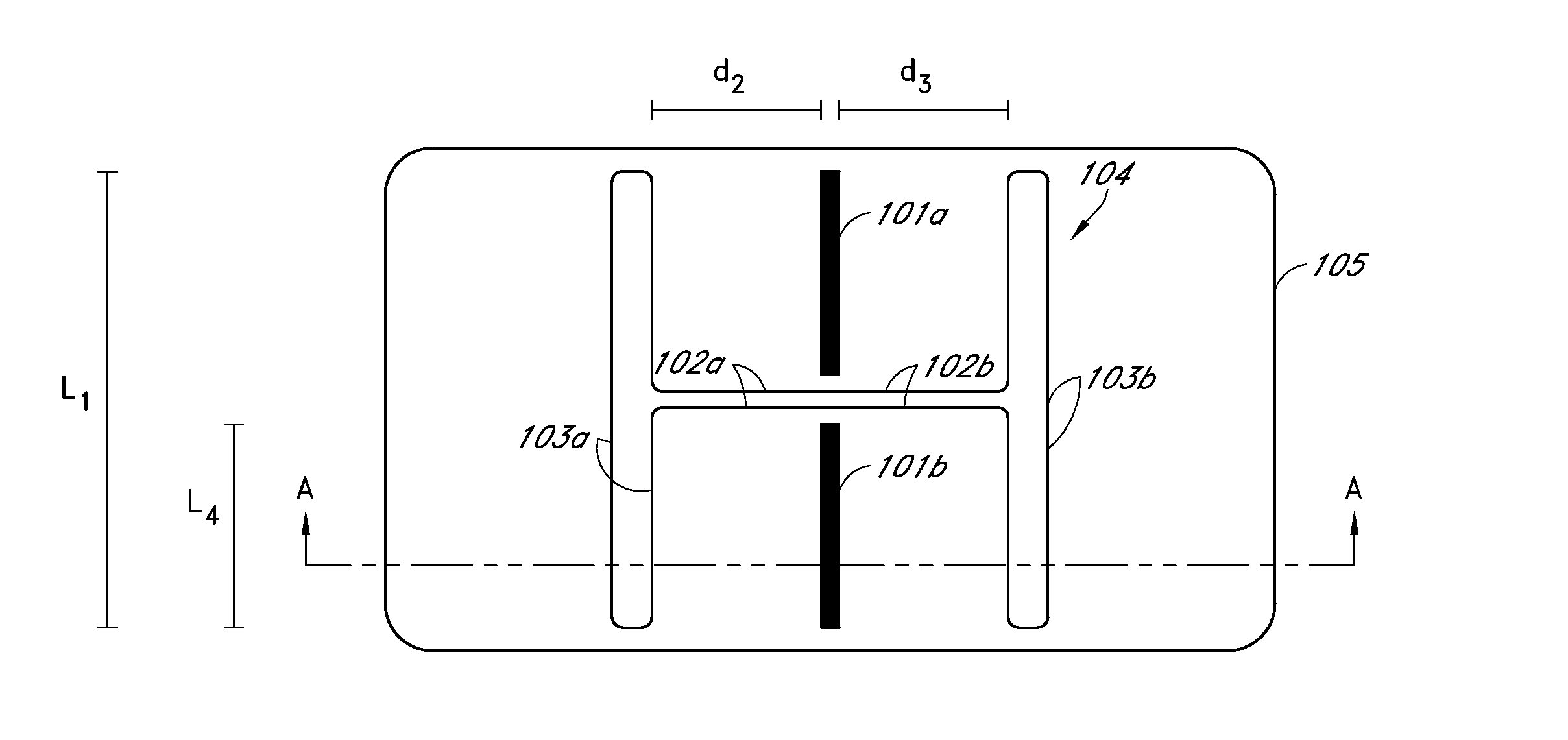
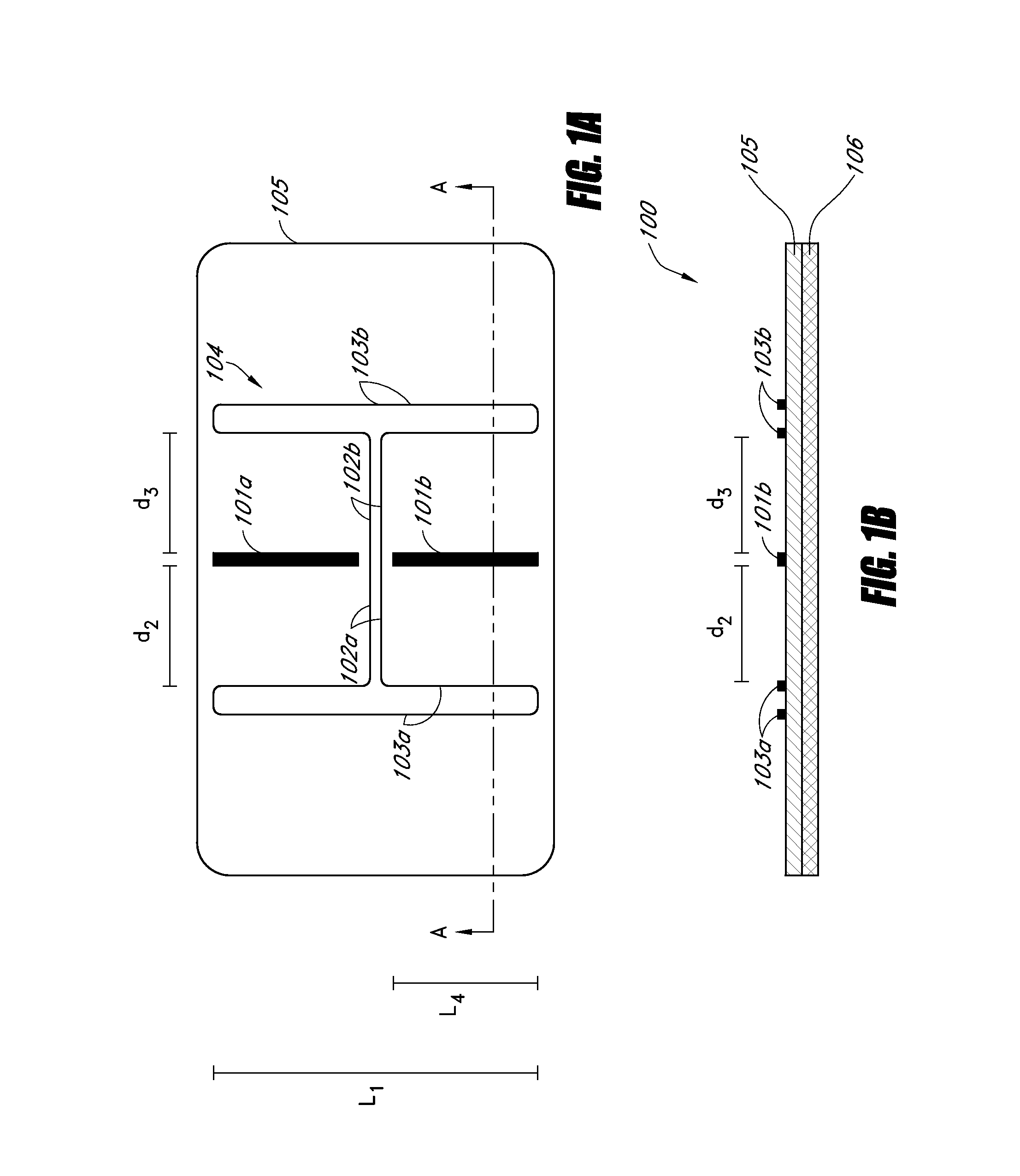
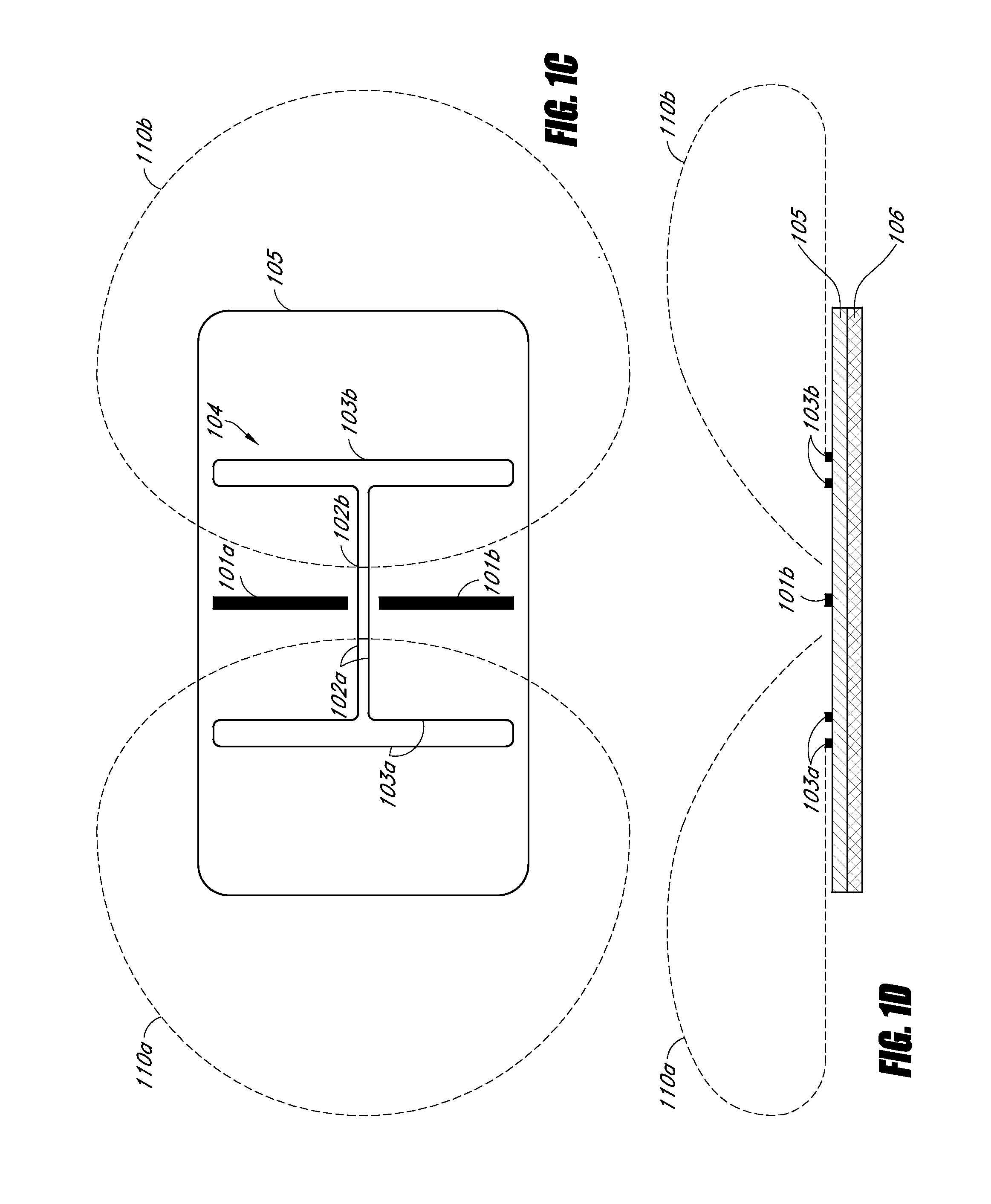
[0010]In some embodiments, an antenna apparatus includes an electromagnetically reflective layer plane, the electromagnetically reflective layer having first and second faces; a first dielectric layer disposed on the first face of the electromagnetically reflective layer; and a first arrangement of conductors disposed on the first dielectric layer. The first arrangement of conductors can include a first resonator including a first antenna having a respective feed point, a second antenna having a respective feed point, and a first coupling element electrically connecting the respective feed points of the first and second antennas. The first arrangement of condu...


PUM


Abstract

Some embodiments provide a relatively small antenna apparatus that acts as a passive repeater. The antenna apparatus can be designed to facilitate radio frequency (RF) signal gain for a collection or range of frequencies. In some embodiments, the antenna apparatus is placed near a device with a wireless receiver and / or transmitter, where the antenna apparatus causes increased RF signal intensity at the device by coupling RF signals from a proximate area of higher RF signal intensity into the area around the device. Accordingly, in some instances, an embodiment of the antenna apparatus can be used to increase the RF signal intensity in a null spot or dead spot by coupling RF signal energy from an area proximate to the null spot that has higher RF signal intensity.

Description

INCORPORATION BY REFERENCE TO ANY PRIORITY APPLICATIONS[0001]Any and all applications for which a foreign or domestic priority claim is identified in the Application Data Sheet as filed with the present application are incorporated by reference under 37 CFR 1.57 and made a part of this specification.BACKGROUND[0002]1. Field[0003]This disclosure relates to wireless communications and to passive repeaters for wireless communications.[0004]2. Description of Related Art[0005]Growing demand for high-rate wireless data services continues to drive the growth of wireless networks. One factor fostering the rapid growth of wireless networks is the growing demand for high-rate data services to be accessible from virtually any location, at all times.[0006]However, despite the efforts of network operators and consumer equipment makers to provide seamless wireless communication coverage, areas of weak signal strength still exist, even in richly serviced areas such as urban centers. The areas of w...

Claims


Application Information

Patent Timeline
Patent Type & Authority Applications(United States)
IPC IPC(8): H01Q19/10
CPCH01Q19/10H01Q19/108H01Q9/16H01Q19/30H01Q25/005H04B7/145H01Q19/06
Inventor WALKER, MICHAEL CLYDE
Owner WALKER MICHAEL CLYDE
Why Eureka
Eureka Blog
Learn More