Inverted Evaporation Apparatus

Inactive Publication Date: 2013-10-31
AREESYS TECH
View PDF6 Cites 0 Cited by
  • Summary
  • Abstract
  • Description
  • Claims
  • Application Information

AI Technical Summary

Benefits of technology

The present invention provides a deposition apparatus that can minimize deformation of substrate, simplify substrate transport mechanism, and provide refined control of vapor flux. The apparatus can improve deposition uniformity, increase materials utilization, maximize deposition on the substrate, and minimize deposition on chamber walls. The apparatus has fine control of temperature field or profile inside the crucible or boat to avoid material spitting and defects in the deposited films. The apparatus is compatible with different substrate positions and can increase energy efficiency and controllability of temperature. The method includes positioning the substrate below or on top of the evaporation source, controlling the temperature of the substrate and the source enclosure, heating a space between the source enclosure and the substrate, and producing a temperature distribution in the substrate. The apparatus can allow the source material to be deposited across different portions of the deposition surface.

Problems solved by technology

One challenge facing deposition of evaporated source material is that it is difficult to ensure uniform deposition on the substrate, especially on large substrates.
Another challenge associated with the conventional system is that the substrate often softens and sags when is heated during deposition.
In a conventional system, there is little or no accurate control of the temperature gradient or temperature field inside the crucible or boat.
It is also difficult to achieve high materials utilization while minimizing wasted material deposition on chamber walls.

Method used


Image

  • Inverted Evaporation Apparatus
  • Inverted Evaporation Apparatus
  • Inverted Evaporation Apparatus

Examples


Embodiment Construction

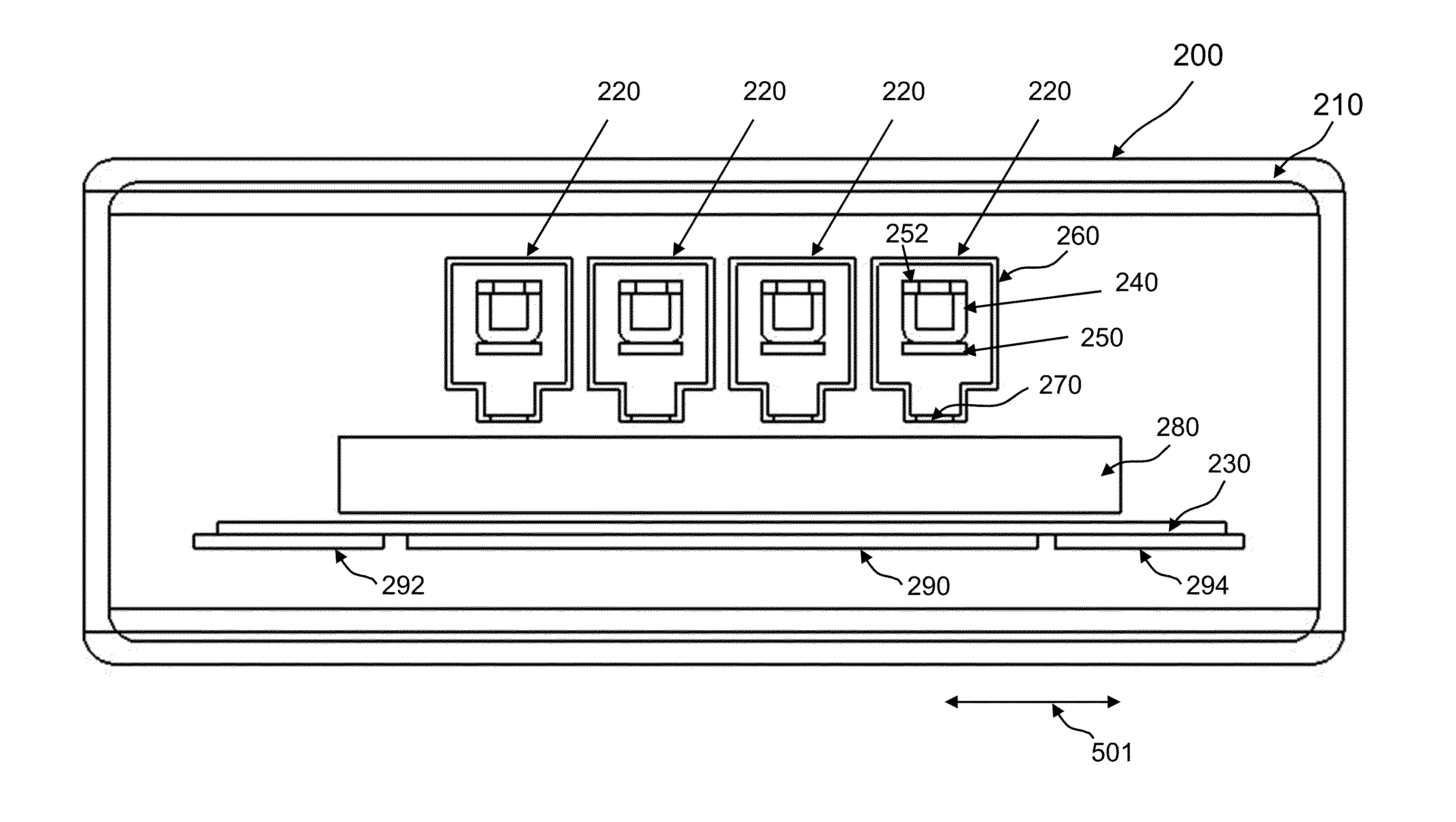
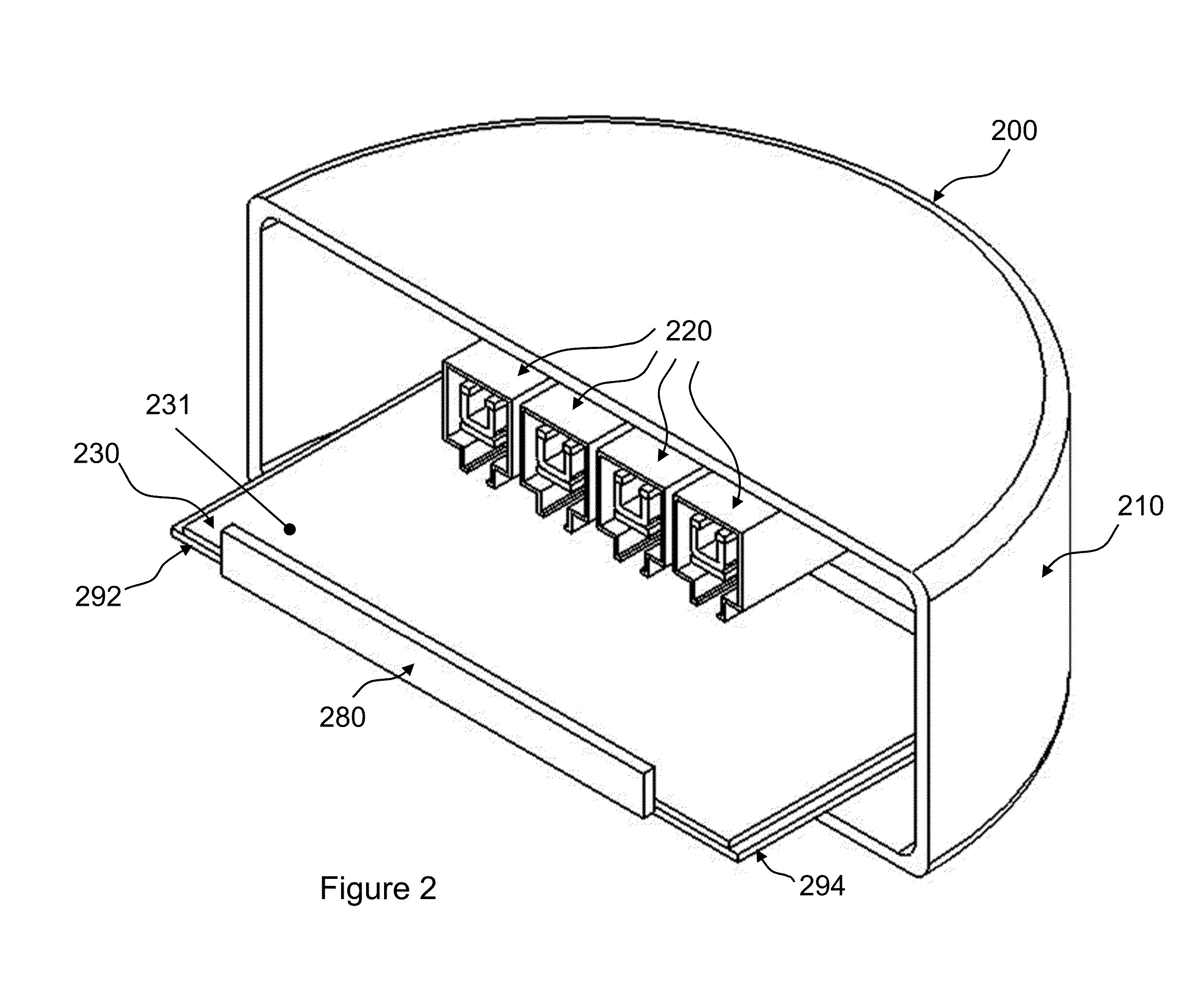
[0020]In some embodiments, referring to FIGS. 2-4, an inverted evaporation apparatus 200 includes a vacuum chamber 210, one or more inverted evaporation sources 220 positioned inside the vacuum chamber 210, and a substrate 230 positioned below one or more inverted evaporation sources 220. Each inverted evaporation source 220 can produce vapor flux that is channeled from the top to the bottom towards the substrate 230 to allow the vapor to condense onto the substrate 230 and deposit the source material onto the substrate 230.

[0021]The inverted evaporation source 220 includes a boat 240 (i.e. a container with opening) for containing a source material and one or more heaters 250, 252 configured to heat and vaporize the source material. The source material and one or more heaters are enclosed in a source enclosure 260 with a vent 270 at the bottom. The source enclosure 260 includes one or more closed walls which, together with boat 240, defines flow path(s) (as indicated by the wide arr...


PUM

PropertyMeasurementUnit
Temperatureaaaaaaaaaa
Flow rateaaaaaaaaaa
Vapor pressureaaaaaaaaaa

Abstract

A deposition apparatus includes one or more evaporation sources each of which includes a container comprising an opening and configured to hold a source material, a source heater adjacent to and in thermal communication with the container, wherein the source heater is configured to elevate temperature of the source material to produce a vapor of the source material, and a source enclosure that encloses the container and the source heater. The source enclosure includes a vent configured to direct the vapor of the source material towards a substrate. The deposition apparatus includes also a plurality of substrate heaters in thermal communication with the substrate. The substrate includes a deposition surface configured to receive deposition of the source material by condensing the vapor. The plurality of substrate heaters can heat different portions of the substrate to different temperatures.

Description

BACKGROUND OF THE INVENTION[0001]The present application relates to material deposition technologies, and more specifically to evaporation deposition systems.[0002]A conventional evaporation deposition system 100, referring to FIG. 1, includes a vacuum chamber 105 that can be evacuated by a pump system 107. A substrate 110 is positioned at the top. One or more evaporation sources 120 are positioned at the bottom. Vapors are produced at evaporation sources 120, and rise to the top. The evaporation sources 120, for example, can contain Sn and S source materials. Each source material can be heated by a heating element 125 (often also acting as a crucible or material loading “boat”) to generate vapor that moves upward. A PID (proportional-integral-derivative) controller 115 is used to control a substrate heater 117, which is placed above the substrate 110. The PID controller is used because it is considered to have better control accuracy and faster response than most simple temperature...

Claims


Application Information

Patent Timeline
IPC IPC(8): C23C16/448
CPCC23C16/4485C23C14/24C23C14/243C23C14/541
Inventor WANG, KAI-ANTING, ALBERTLIN, ENHAOWONG, MICHAEL
Owner AREESYS TECH
Why Eureka
Try Eureka