Developing apparatus and process cartridge

a technology of developing apparatus and process cartridge, which is applied in the direction of electrographic process apparatus, instruments, optics, etc., can solve the problems of preventing the extension of life, affecting the quality of the image,

Inactive Publication Date: 2013-10-31
CANON KK
View PDF29 Cites 1 Cited by
  • Summary
  • Abstract
  • Description
  • Claims
  • Application Information

AI Technical Summary

Benefits of technology

The patent describes a problem with solid image follow-up failure in the printing process. The problem is caused by a narrow toner taking-in region in the distal end portion of the regulating blade, which results in insufficient formation of a coat on the developing roller when the pre-coat is sparse. The patent also discusses the results of a verification of fog levels in a low-temperature and low-humidity environment, where no fog was present. The technical effect of the patent is to address the problem of solid image follow-up failure by improving the quality of the coat formed on the developing roller during the printing process.

Problems solved by technology

However, as disclosed in Japanese Patent Application Laid-Open No. 2006-208619, in the developing apparatus in which the developing roller and the feed roller are arranged so that the respective surfaces move in the forward direction in the abutment portion therebetween, solid image follow-up failure in which the density of a trailing edge of an image becomes lower may occur.
Although the foregoing measure can solve the problem of solid image follow-up failure, there arises the following problem particularly in an image forming apparatus having high productivity and a high image forming speed.
When the degradation of toner, that is, the isolation and embedding of an external additive on a toner surface is accelerated, a degree of compaction increases and toner chargeability decreases, and a problem such as toner filming in which a toner is fused onto the developing roller occurs, which prevents extension of life.

Method used


Image

  • Developing apparatus and process cartridge
  • Developing apparatus and process cartridge
  • Developing apparatus and process cartridge

Examples


embodiment 1

[0030]In an embodiment of the present invention described below, a developing apparatus to be used in an image forming apparatus will be described in an illustrative manner.

[0031](1) Overview of Configuration and Operation of Image Forming Apparatus

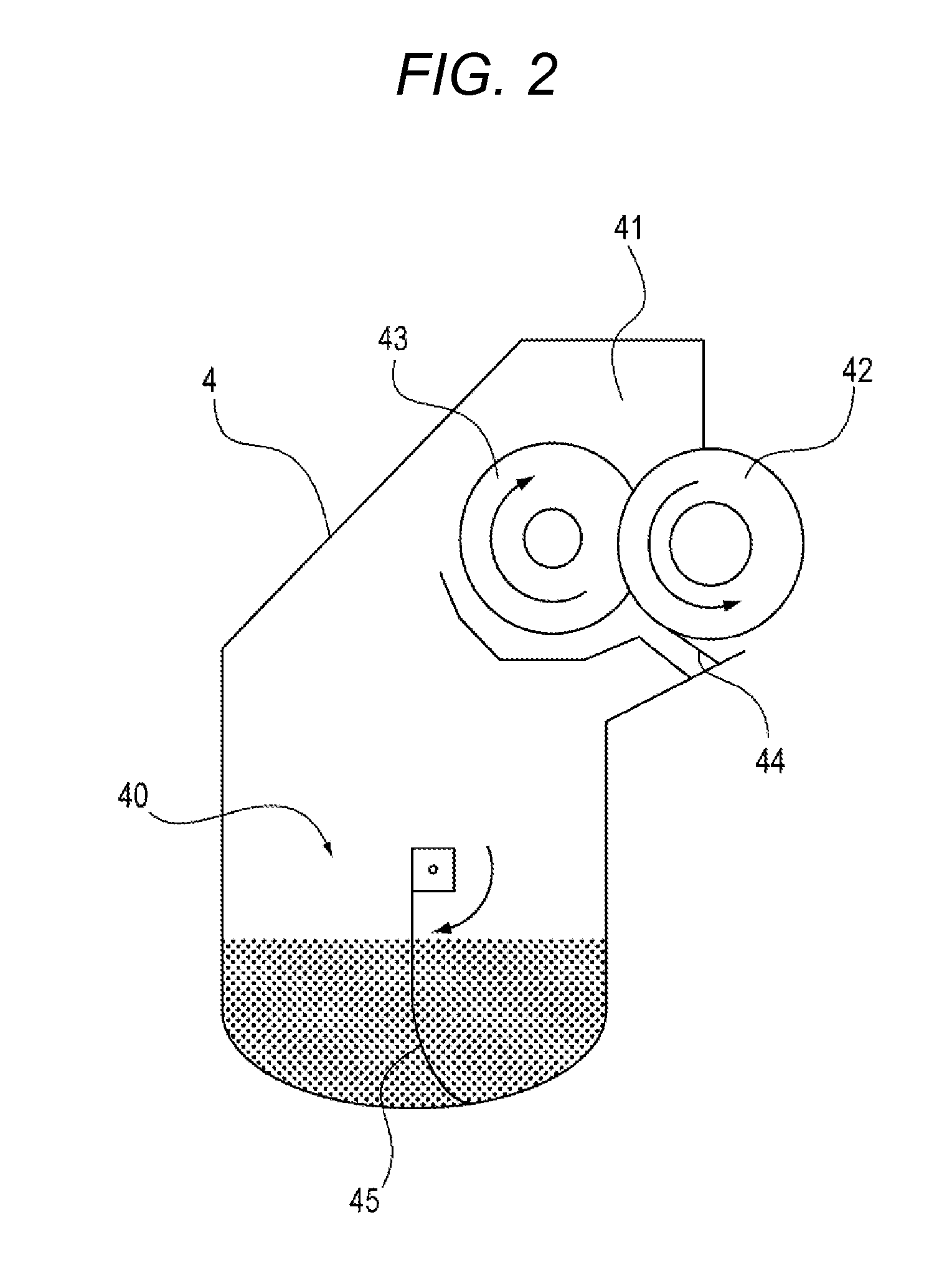
[0032]FIG. 1 is a structural view illustrating an entire schematic configuration of an image forming apparatus according to Embodiment 1. The image forming apparatus includes a charging roller 2, an exposure device 3, a developing apparatus 4, a transfer belt 5, and a cleaning device 6 arranged in this order around a drum-shaped photosensitive drum 1 which is an image bearing member. The charging roller 2 is a charging unit configured to uniformly charge the surface of the photosensitive drum 1. The exposure device 3 is an exposure unit configured to irradiate the photosensitive drum 1 with laser light modulated according to image information. The developing apparatus 4 is a developing unit configured to develop an electrostatic latent im...

embodiment 2

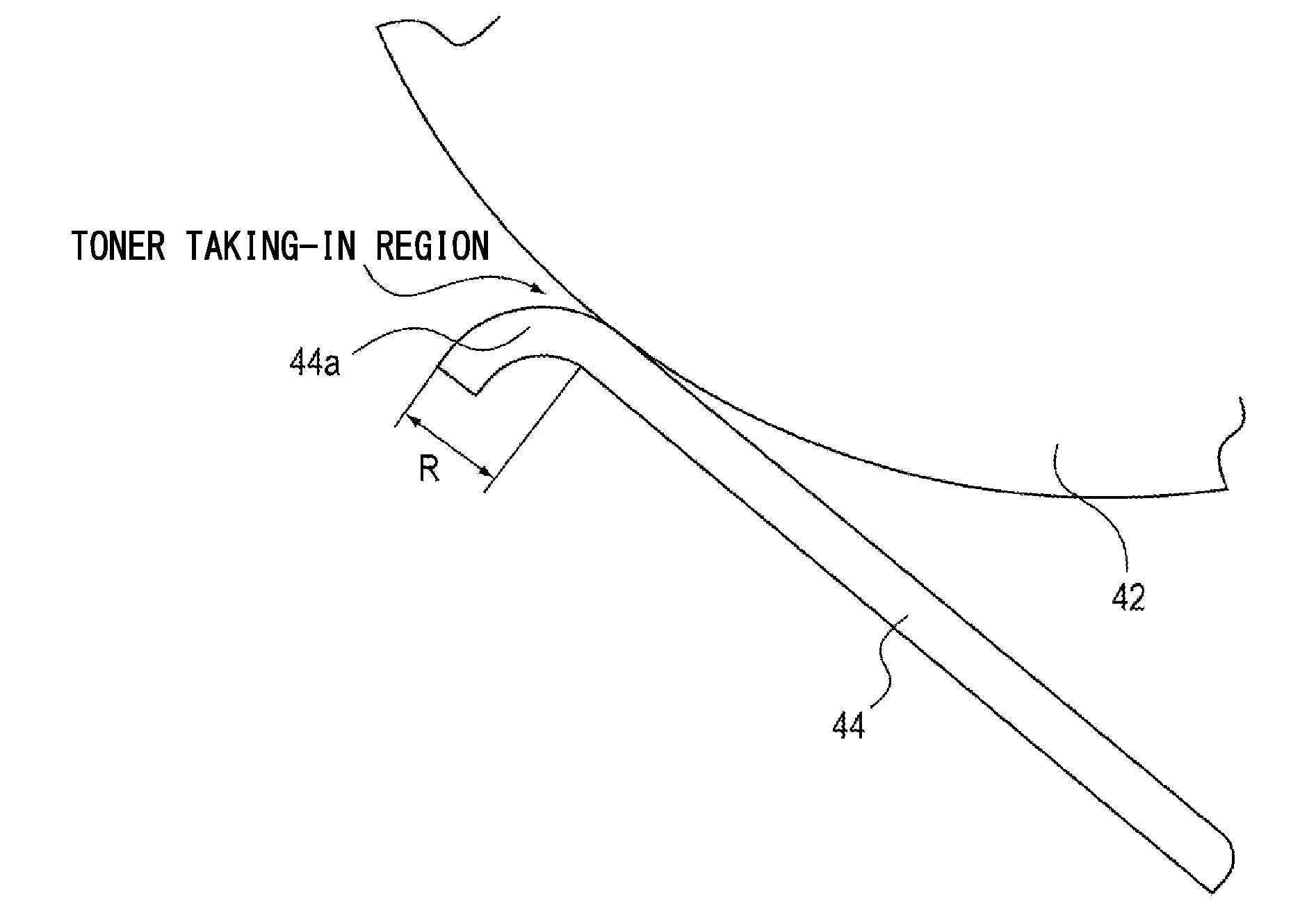
[0086]As illustrated in FIG. 8, the regulating blade 44 of Embodiment 2 of the present invention has a configuration in which a distal end portion that abuts on the developing roller 42 is formed by applying an insulating elastomer 44c to an end portion of a support 44b. The configuration and effect of the regulating blade 44 using the insulating elastomer of Embodiment 2 will be described by way of comparative examples. The regulating blade 44 used in Embodiment 2 is a regulating blade disclosed in Japanese Patent Application Laid-Open No. 2008-090160 in which the support 44b of a metallic SUS plate having a thickness of 0.1 mm is coated with the polyamide elastomer 44c as an insulating elastomer.

[0087]Table 3 shows results obtained by determining a fog level with respect to VSP / VDR in Embodiment 2. An experiment was performed in an environment of a temperature of 15° C. and a humidity of 10%. Regulating blades (SUS blades) provided with distal end portions having curvature radii R...

embodiment 3

[0095]In Embodiment 3 of the present invention, a configuration will be described in an illustrative manner, in which a bias is applied to a regulating blade through use of an elastomer that is provided with conductivity by the addition of an electro-conductive agent. The shape of the regulating blade of the embodiment was the same as that illustrated in FIG. 8 and had a volume resistivity of 1×10⁶ Ω·cm to 1×10⁹ Ω·cm obtained by adding an ionic electro-conductive agent to a polyamide elastomer as an electro-conductive resin. As a blade bias, a voltage of −400 V was applied to the support (SUS plate) 44b of the regulating blade 44 illustrated in FIG. 8 with respect to a developing bias of −300 V to be applied to the cored bar of the developing roller, to thereby provide a potential difference of −100 V.

[0096]FIG. 9 shows results obtained by verifying a relationship of the amount of coat after passing through the regulating blade with respect to the VSP / VDR so as to show the effects o...


PUM


Abstract

A developing apparatus, including: a developer carrying member; a developer feeding member configured to feed the developer to the developer carrying member in abutment with the developer carrying member; and a developer regulating member having a distal end portion directed toward an upstream side in a rotation direction of the developer carrying member, and configured to regulate a layer thickness of the developer on the developer carrying member in abutment with a surface thereof. Surfaces of the developer carrying member and the developer feeding member move in the same direction in an abutment portion. The distal end portion of the developer regulating member has a developer taking-in portion away from the surface of the developer carrying member toward the upstream side in the rotation direction. The developer taking-in portion is positioned upstream of an abutment position between the developer regulating member and the developer carrying member.

Description

BACKGROUND OF THE INVENTION[0001]1. Field of the Invention[0002]The present invention relates to a developing apparatus configured to develop an image with use of developer, a cartridge including the developing apparatus, and an image forming apparatus using the developing apparatus.[0003]2. Description of the Related Art[0004]Conventionally, as a developing apparatus configured to visualize an electrostatic latent image through use of one-component toner, there is known a developing apparatus including a developing roller serving as a developer carrying member configured to carry and convey toner, and a feed roller serving as a developer feeding member, arranged at a position on the periphery of the developing roller, configured to feed toner to the developing roller.[0005]In the developing apparatus, toner is fed to the developing roller while becoming charged triboelectrically by mechanical rubbing between the feed roller and the developing roller. The fed toner has a toner layer...

Claims


Application Information

Patent Timeline
IPC IPC(8): G03G15/08
CPCG03G15/0812G03G15/081
Inventor MITSUI, YOSHIHIROYOSHIDA, NOBUYOSHIHAYASHI, KODAITANIGUCHI, HISASHI
Owner CANON KK
Why Eureka
Try Eureka