Eureka AIR delivers breakthrough ideas for toughest innovation challenges, trusted by R&D personnel around the world.

System and method for detecting broken rail and occupied track from a railway vehicle

a technology for railway vehicles and broken rails, applied in railway signalling, railway components, transportation and packaging, etc., can solve problems such as short circuit, unintentional misalignment of turnouts, and occupied tracks presenting potential hazards to moving trains, and achieves significant reductions in the required track infrastructure and ongoing maintenance costs, and achieves operational performance advantages

Active Publication Date: 2013-10-31
TRANSPORTATION TECH CENT
View PDF17 Cites 74 Cited by
  • Summary
  • Abstract
  • Description
  • Claims
  • Application Information

AI Technical Summary

Benefits of technology

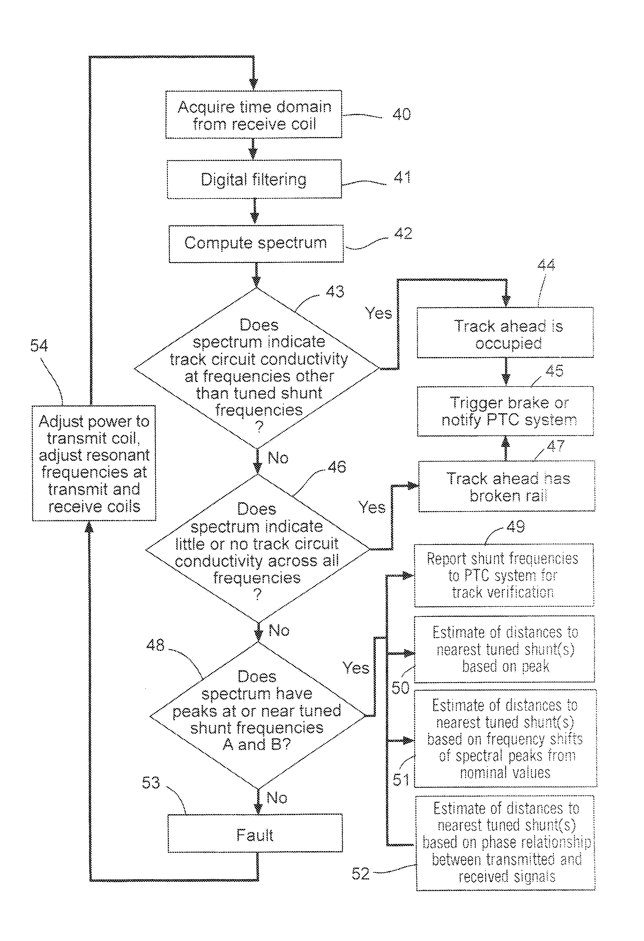
The present invention is a system and method for detecting rail breaks or track occupancy from a moving or static railroad locomotive or rolling stock. This is done by analyzing data from GPS, track circuits, and other sources to provide a better estimate of train location and speed. The invention can interface with existing CBTC or PTC systems to notify the operator and trigger brakes or track occupancy detection. The invention reduces the need for expensive fixed infrastructure and maintenance costs. The technical effect is improved safety and efficiency in detecting track issues and improving train location information.

Problems solved by technology

Rail breaks, unintentionally misaligned turnouts, and occupied track present potential hazards to moving trains.
The absence of current indicates that either a broken rail or open switch is causing an electrical open circuit, or that the presence of a train is shunting current between the rails, causing a short circuit.
A fundamental limitation of such traditional fixed-block wayside signaling systems is that by dividing railroad track into discrete blocks, they impose a limit on how closely trains can approach each other and still sense both broken rail and occupied territory ahead; thus they artificially limit maximum traffic density and therefore fundamentally restrict how efficiently a given track can be utilized.
A second fundamental limitation of traditional fixed-block track circuit systems is their inherent inability to detect a rail break which occurs ahead of or behind a moving train within the same block as the train.
Also undetectable with track circuits is a rail break between two trains in the same block.
A third fundamental limitation of traditional track circuits is that they require installation of considerable track infrastructure, such as insulated joints between blocks, bond wires to ensure continuity between rail sections, wayside power, and wayside relay-based, code-relay, or (more commonly) electronic systems.
This infrastructure and equipment is costly to install and requires very significant ongoing maintenance.
A fourth fundamental limitation of traditional track circuits is that they are not usually optimized to detect rail breaks, but instead are optimized for wayside signal system operation.
A limitation of some implementations of PTC or CBTC systems that employ GPS data to determine which track a train is travelling on in multiple track territory is that even the best available GPS systems are unable to reliably distinguish which of two adjacent tracks a train is occupying with sufficient accuracy to be considered certain for safety-critical applications.

Method used


Image

  • System and method for detecting broken rail and occupied track from a railway vehicle
  • System and method for detecting broken rail and occupied track from a railway vehicle
  • System and method for detecting broken rail and occupied track from a railway vehicle

Examples


Embodiment Construction

[0043]Before describing in detail the system and method for detecting broken rail or occupied track from a moving locomotive, it should be observed that the present invention resides primarily in what is effectively a novel combination of conventional electronic circuits, electronic components, and signal processing / estimation algorithms, and not in the particular detailed configurations thereof. Accordingly, the structure, control, and arrangement of these conventional circuits, components, and algorithms have been illustrated in the drawings by readily understandable block diagrams which show only those specific details that are pertinent to the present invention, so as not to obscure the disclosure with structural details which will be readily apparent to those skilled in the art having the benefit of the description herein. Thus, the block diagram illustrations of the figures do not necessarily represent the mechanical structural arrangement of the exemplary system, but are prim...


PUM


Abstract

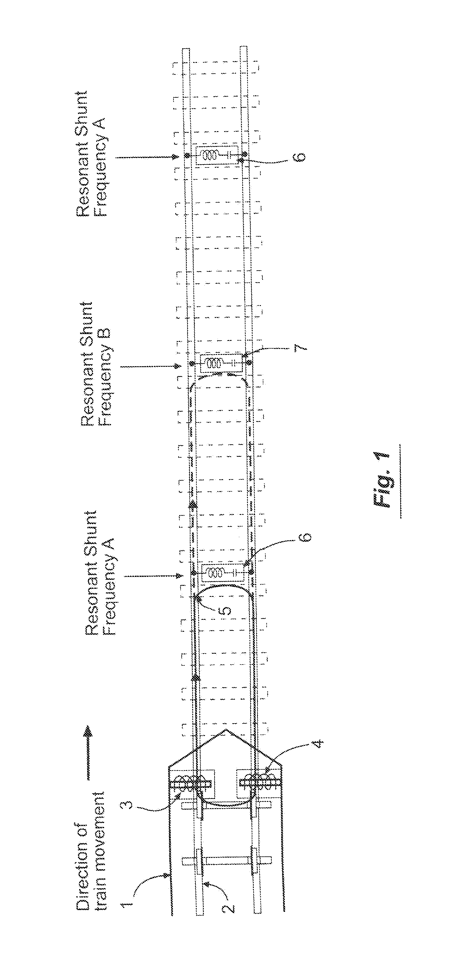
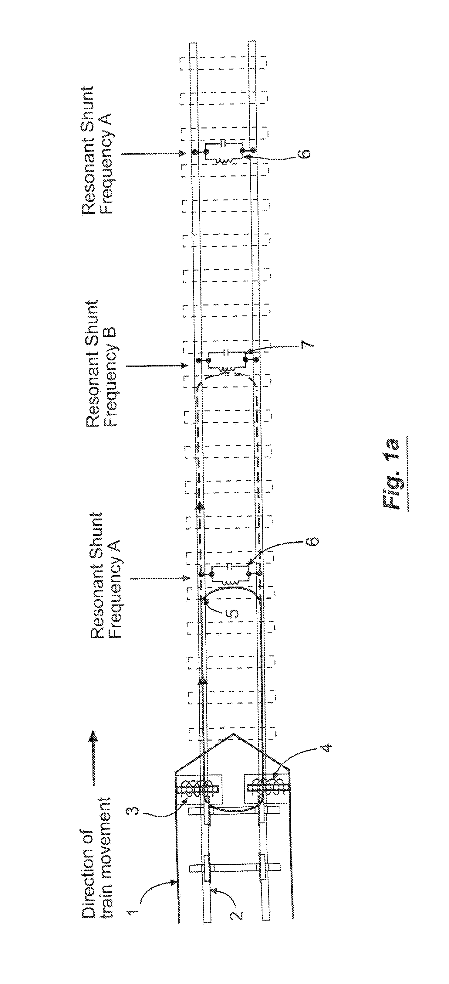
A method is provided for detecting broken rail, unintentionally misaligned turnouts, and track occupancy ahead of or behind a railway vehicle traveling on a railroad track. Shunts extend between the rails at intervals along the railroad track. Each shunt has electrical signal transmission characteristics differing from those of adjacent shunts. A test unit on the railway vehicle induces a test signal in a first rail to create a track circuit in which the test signal propagates along the first rail, through at least one of the shunts, returns to the railway vehicle along the second rail, and through the wheels and axle of the railway vehicle. The test signal has electrical properties selected to interact with at least one of the shunts. The received test signal on the second rail is analyzed to identify predetermined conditions concerning the status of the railroad track.

Description

RELATED APPLICATION[0001]The present application is based on and claims priority to the Applicants' U.S. Provisional Patent Application 61 / 639,256, entitled “System and Method for Detecting Broken Rail and Occupied Track from a Railway Vehicle,” filed on Apr. 27, 2012.BACKGROUND OF THE INVENTION[0002]1. Field of the Invention[0003]The present invention relates generally to safety and efficiency of train movement. More particularly, the present invention is in the field of railroad signaling and train control, including positive train control (PTC), centralized traffic control (CTC), automatic block signaling (ABS), and communications-based train control (CBTC).[0004]2. Background of the Invention[0005]Rail breaks, unintentionally misaligned turnouts, and occupied track present potential hazards to moving trains. Traditionally, rail breaks, misaligned turnouts and occupied track are directly detected by use of track circuits. Railroad track is physically divided into electrically dis...

Claims


Application Information

Patent Timeline
Patent Type & Authority Applications(United States)
IPC IPC(8): B61L27/00
CPCB61L27/0055B61L3/243B61L21/10B61L23/044B61L25/021B61L25/023B61L25/026B61L2205/04B61L1/188B61L27/60
Inventor POLIVKA, ALAN LEEMALONE, JR., JEROME J.SMITH, BRIAN ERICRENFROW, STEVEN MARK
Owner TRANSPORTATION TECH CENT
Why Eureka
Eureka Blog
Learn More