Gas-particle processor

a gas-particle processor and gas-particle technology, applied in the field of gas-particle processing and gas-particle processors, can solve the problems of increased pressure drop, inefficiency of gas-solid contactors, and their own deficiencies, so as to reduce space and cost requirements, the effect of reducing space and cost requirements

Active Publication Date: 2013-10-31
APRIL PTY LTD
View PDF12 Cites 2 Cited by
  • Summary
  • Abstract
  • Description
  • Claims
  • Application Information

AI Technical Summary

Benefits of technology

The patent describes a processor that can control the flow of gas and particles through a chamber to achieve a high level of porosity. This means that the particles in the stream are not hindering each other, allowing for increased access to their surface by the gas. The gas-particle processor operates on a multi-stage process, where each particle passes through the gas multiple times. This reduces the space and cost requirements compared to multiple processors. The processor also operates at a low pressure drop, minimizing the energy required to accelerate the particles. The small particle size and narrow size distribution provide a high surface area, enhancing exchange processes between the particle and gas streams. Particles with a diameter of less than 300 μm are preferred.

Problems solved by technology

Examples of these systems are rotary dryers and rotary kilns, but these are not efficient gas-solid contactors.
However, these systems have their own deficiencies such as an increased pressure drop and contacting inefficiency.

Method used


Image

  • Gas-particle processor
  • Gas-particle processor
  • Gas-particle processor

Examples


example 1

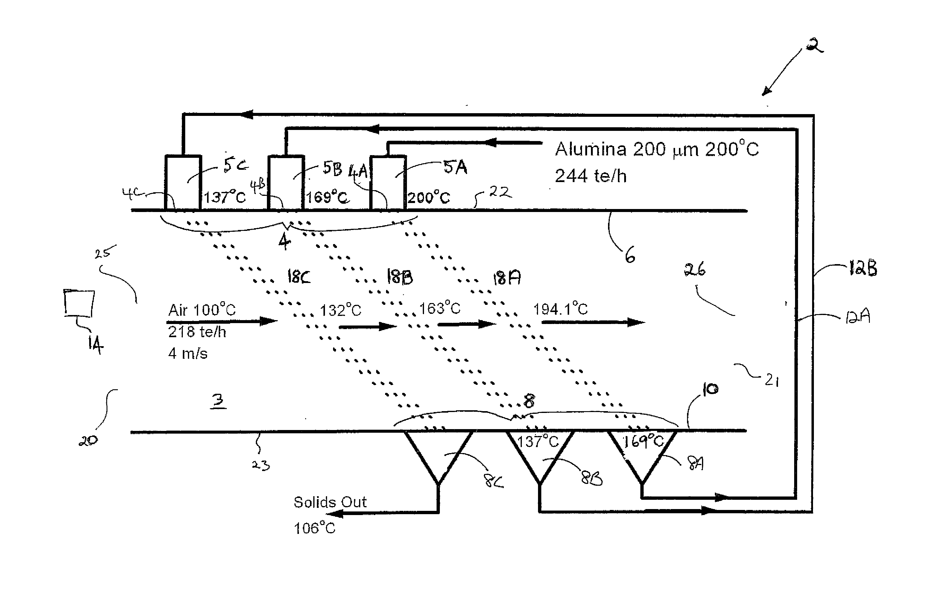
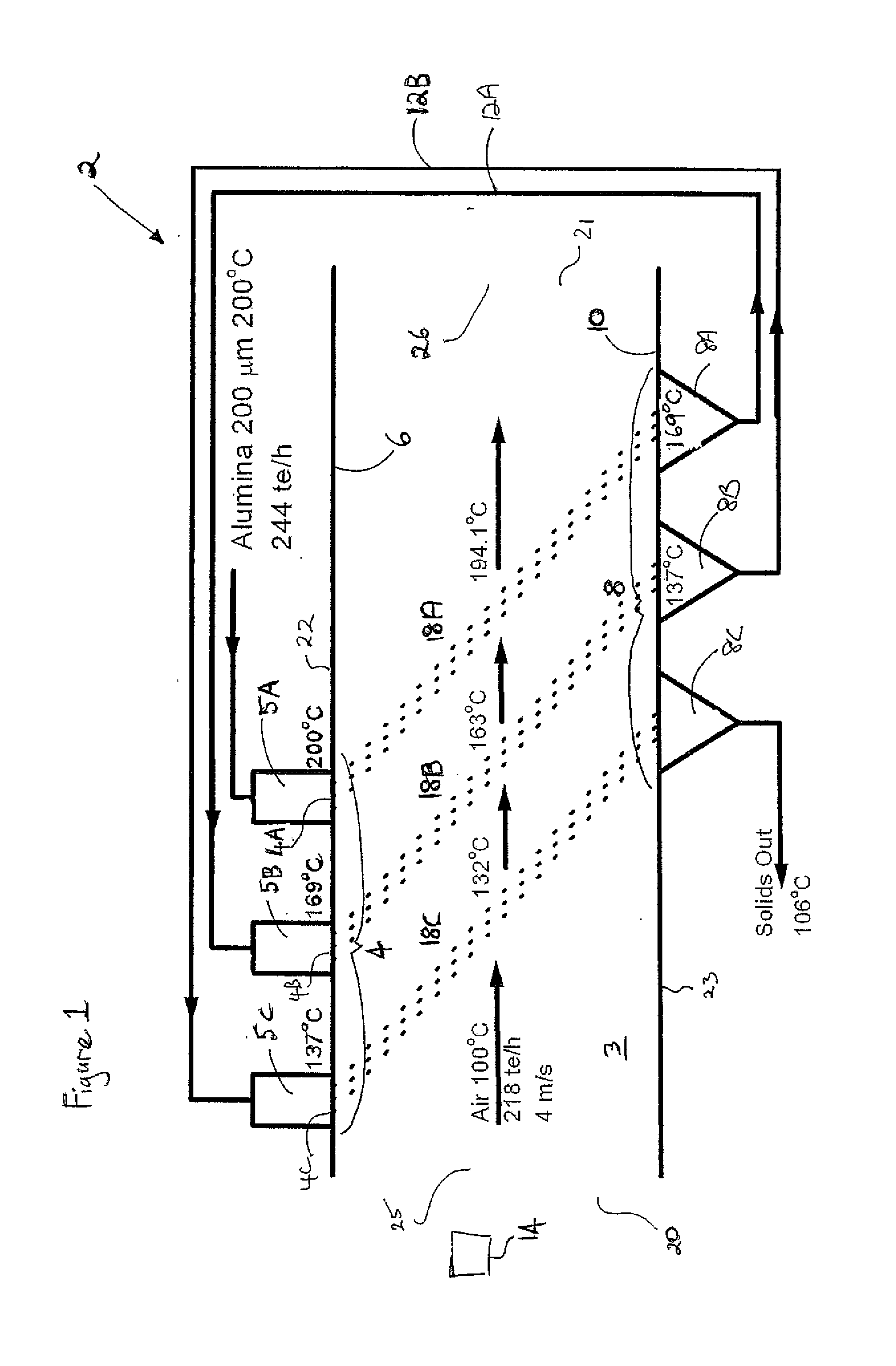
[0151]Gas feeder 14 introduces a stream of gas at a mass flowrate of 218 tonnes / hr, a velocity of 4 m / s and a temperature of 100° C. into a 4 m×4 m chamber. The gas stream exits the chamber from gas outlet 26.

[0152]A stream of alumina particles of 200 μm in diameter, a mass flowrate of 244 tonnes / hr and a temperature of 200° C. is introduced into the chamber from particle feeder 5A.

[0153]As the particles fall through the gas stream, heat exchange occurs between the particle stream and the gas stream at stage 18A. This results in cooling of the alumina stream to 169° C. under ideal conditions. Recycling of this particle stream occurs as it exits through particle outlet 8A and is fed to particle inlet 4B via conduit 12A. For the purposes of this calculation, no or little heat exchange is assumed for the flow in any connecting conduits. The particle stream re-enters processor 2 at stage 18B. Further heat exchange between the particle stream and the gas stream occurs as the temperature ...

example 2

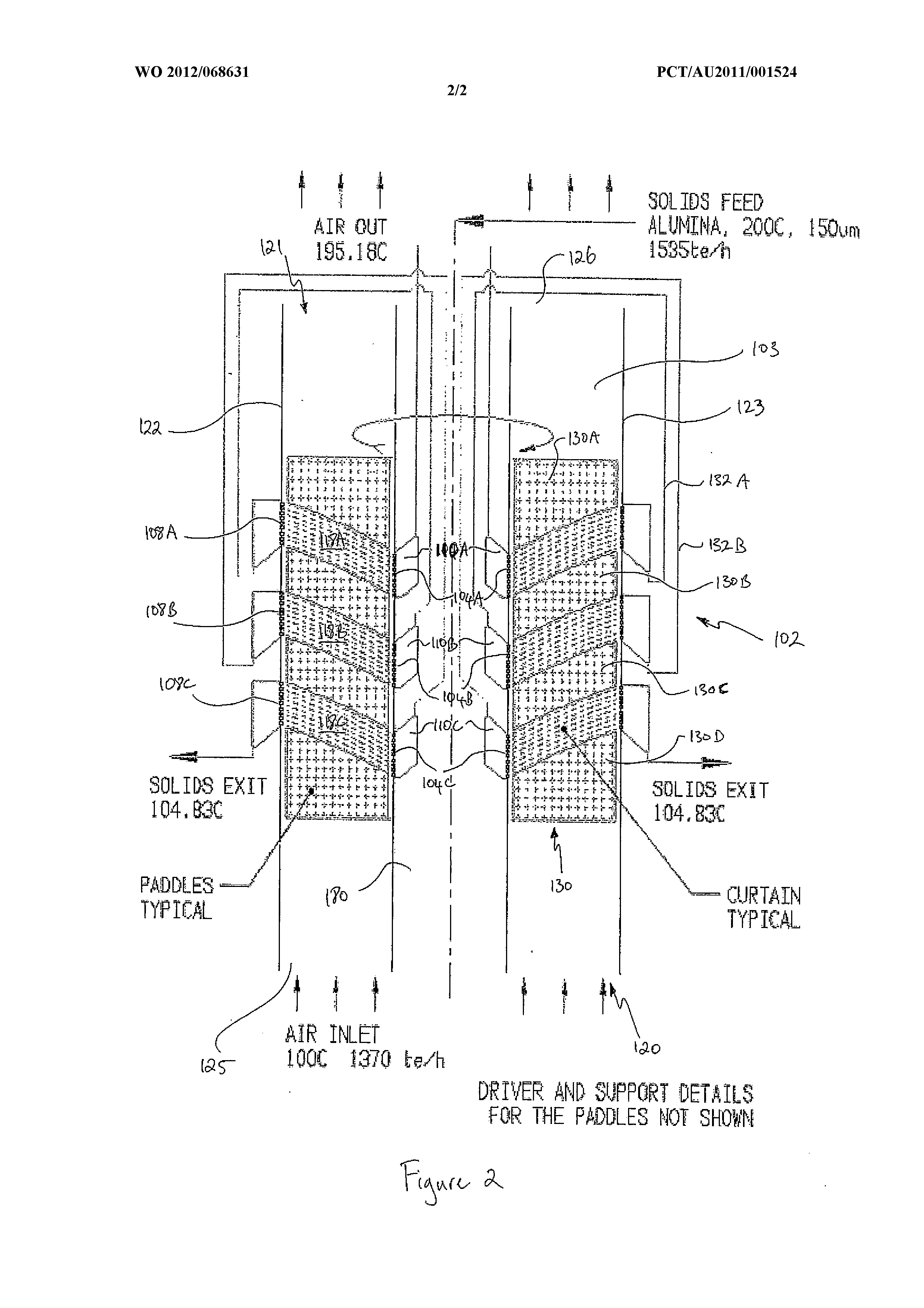
[0155]Gas feeder 114 introduces a stream of gas at a mass flowrate of 1370 tonnes / hr, a velocity of 4 m / s and a temperature of 100° C. into a chamber having a 12 m outer diameter and a central particle feeder member which is 4 m in diameter. The gas stream exits processor 102 from gas outlet 126. Paddles 130A, 130B and 130C are located between processing stages 118A, 118B and 118C to provide a means for gas rotation. Additional paddles 130B, 130D and 130F may be located within stages 118A, 118B and 118C, respectively, which may be also used to regulate the rotational velocity of the gas. These paddles would be in the form of a number of small paddles fixed to a rotating framework.

[0156]A stream of alumina particles of 150 μm in diameter, at a mass flowrate of 1535 tonnes / hr and a temperature of 200° C. is introduced into the chamber from particle feeder 110A.

[0157]As the particles are introduced into the chamber through particle inlet 104A, centrifugal forces imparted by the spirall...


PUM


Abstract

A gas-particle processor comprising: a chamber having a gas inlet, a gas outlet and one or more particle inlets; a gas flow arrangement operable to flow gas through the chamber from the gas inlet to the gas outlet at a first controlled mass flow-rate; and a particle flow arrangement operable to introduce particles in one or more streams into the chamber at a second controlled mass flow-rate, each particle stream flowing through respective processing regions in the chamber, wherein the processor is operable to control the first and / or second controlled mass flow-rates to provide a gas-particle mixture porosity in a substantial portion of each processing region of 0.900-0.995.

Description

TECHNICAL FIELD[0001]This present invention relates to gas-particle processes and gas-particle processors, including processes and processors relating to gas-solid heat and mass transfer, gas-catalyst reactions, gas absorption (in liquid droplets) and cooling towers.BACKGROUND[0002]There are many systems used to conduct gas-solid processes such as gas-particle energy recovery and regeneration, gas-solid chemical reactions, gasification, adsorption, drying, gas absorption and distillation.[0003]Examples of these systems are rotary dryers and rotary kilns, but these are not efficient gas-solid contactors. Other systems such as fluidised beds and circulating fluidised beds have been used instead. However, these systems have their own deficiencies such as an increased pressure drop and contacting inefficiency.SUMMARY OF THE DISCLOSURE[0004]In a first embodiment, there is provided a gas-particle processor comprising:[0005]a chamber having a gas inlet, a gas outlet and one or more particl...

Claims


Application Information

Patent Timeline
Patent Type & Authority Applications(United States)
IPC IPC(8): F26B17/10F26B21/00
CPCF26B17/10F26B21/003B01J8/08B01J8/0015B01J8/005B01J2208/00088B01J2208/00548B01J2208/0084F28C3/12F28D19/02F26B3/0923F26B17/101F26B17/104F26B17/00F26B21/00B65G53/66B65G53/16
Inventor POTTER, OWEN
Owner APRIL PTY LTD
Why Eureka
Try Eureka