Virtual image display apparatus
a display apparatus and virtual image technology, applied in the direction of mechanical pattern conversion, instruments, cathode-ray tube indicators, etc., can solve the problems of wearer discomfort, wearer may even develop motion sickness-like symptoms, uncomfortable sensation resulting from such motion, etc., and achieve the effect of reducing the overall size of the apparatus
- Summary
- Abstract
- Description
- Claims
- Application Information
AI Technical Summary
Benefits of technology
Problems solved by technology
Method used
Image
Examples
first embodiment
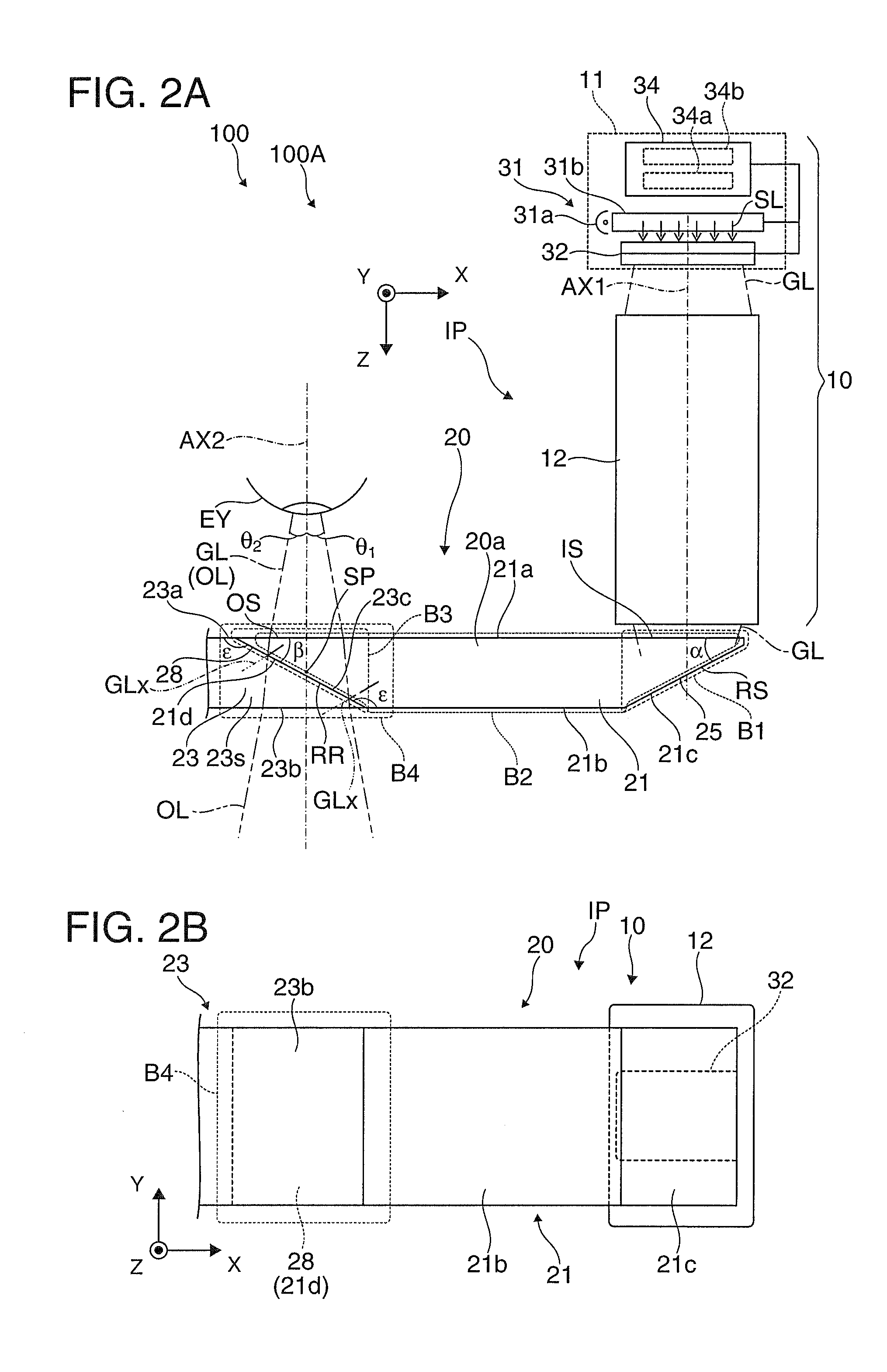
[0033]A virtual image display apparatus according to a first embodiment of the invention will be described below in detail with reference to the drawings.
A. Exterior Appearance of Virtual Image Display Apparatus
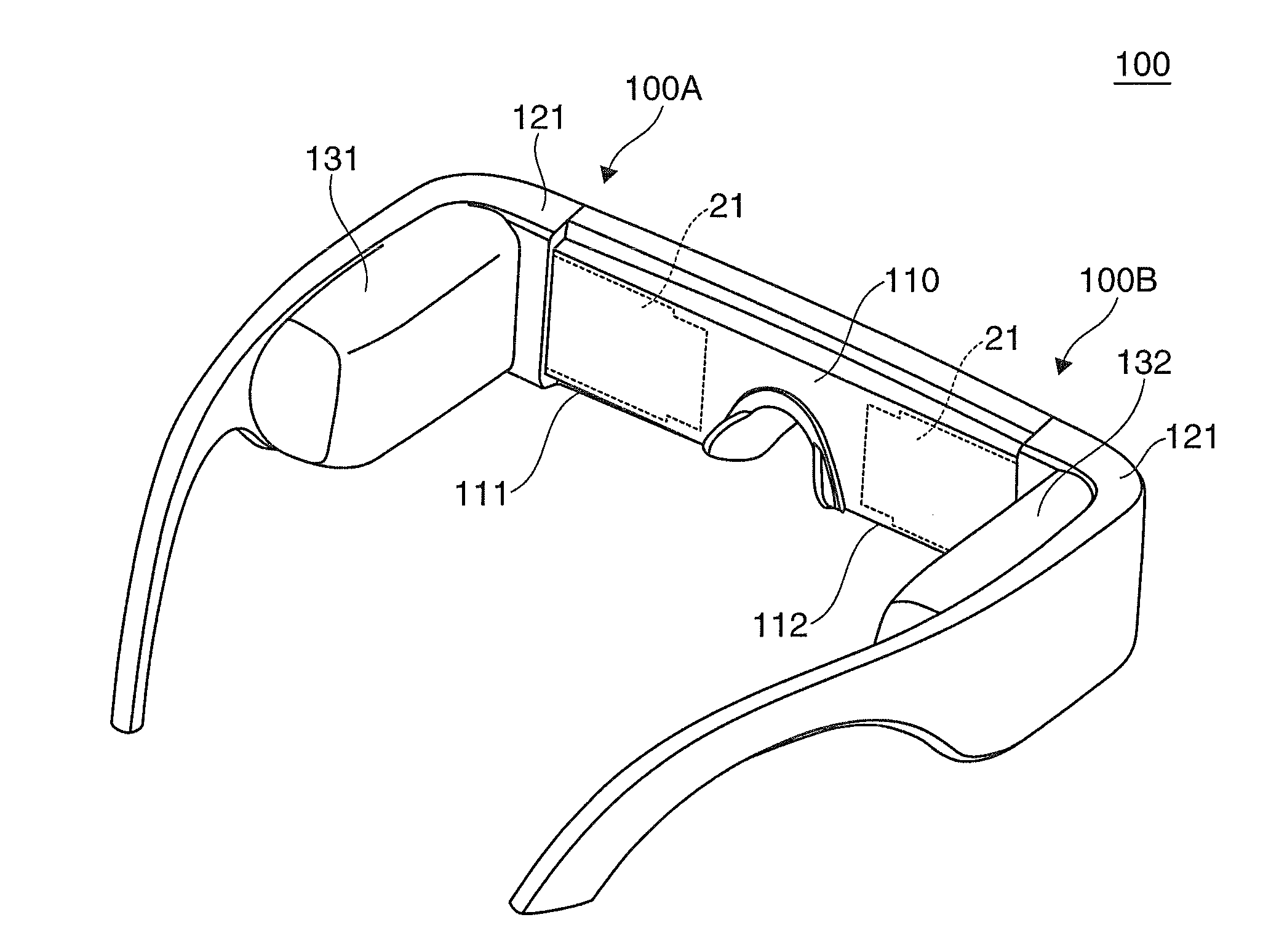
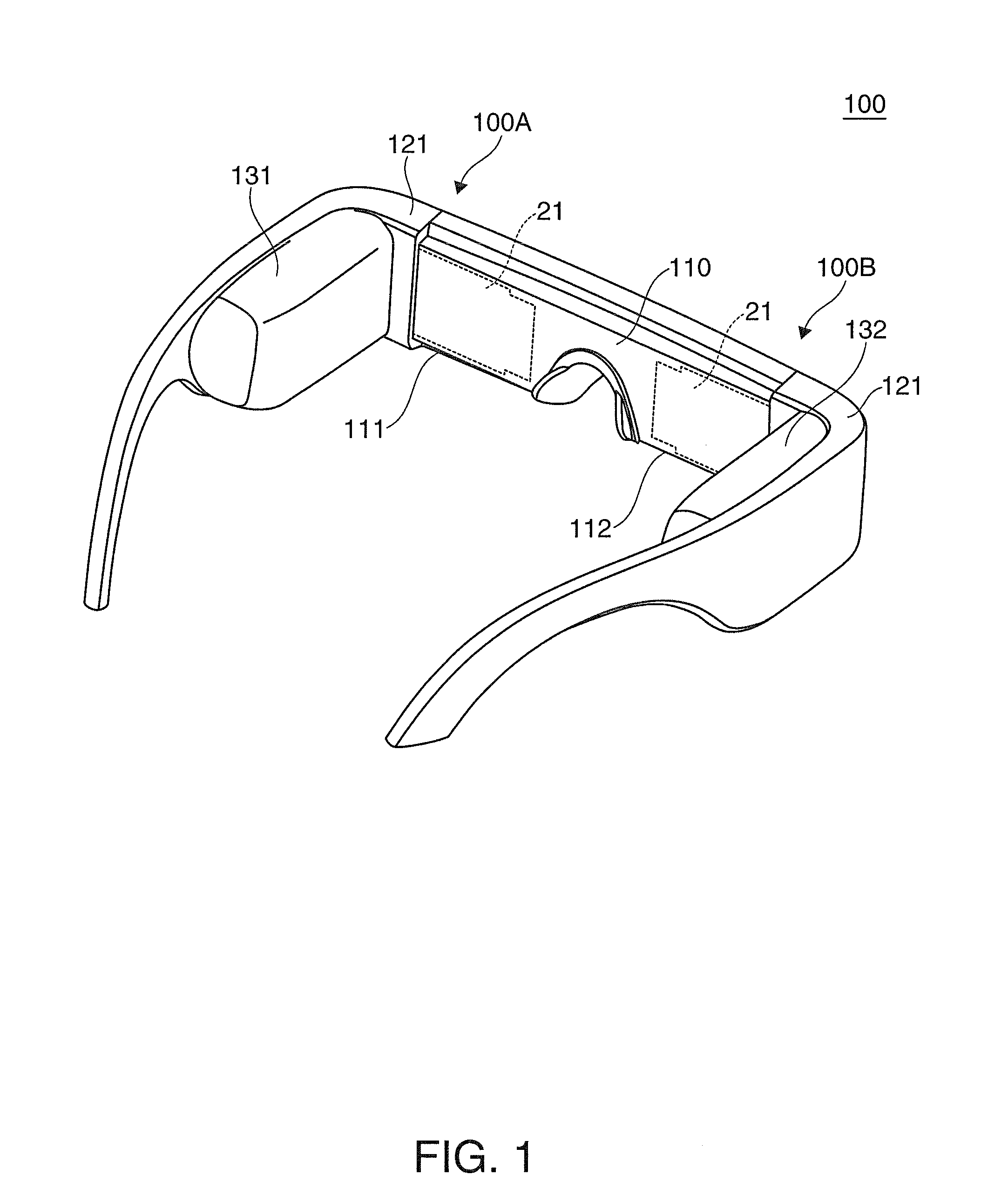
[0034]A virtual image display apparatus 100 according to the present embodiment shown in FIG. 1, which is a head-mounted display having a spectacle-like external appearance, allows a wearer, a viewer wearing the virtual image display apparatus 100, not only to recognize image light in the form of a virtual image but also to view an environment light image in see-through observation. The virtual image display apparatus 100 includes an optical panel 110, which covers a portion in front of the eyes of the wearer, frames 121, which support the optical panel 110 and other components, and first and second drivers 131, 132, each of which is attached to a portion of the corresponding frame 121 that extends from a front-side cover portion to a temple. The optical panel 110 includes a ...
second embodiment
[0075]A virtual image display apparatus according to a second embodiment will be described below. The virtual image display apparatus according to the present embodiment is a variation of the virtual image display apparatus 100 according to the first embodiment and has the same exterior structure as that of the virtual image display apparatus 100 except the image area position adjustment mechanism. No illustration or description of the virtual image display apparatus according to the present embodiment as a whole will therefore be made.
[0076]FIGS. 6A and 6B correspond to FIGS. 4A and 4B in the first embodiment and describe an optical system position drive unit 280, which forms an image area position adjustment mechanism in the virtual image display apparatus according to the present embodiment.
[0077]The optical system position drive unit 280 moves the projection system 12 in the X and Y directions based on a drive signal from the arithmetic processing unit 70.
[0078]As described abov...
third embodiment
[0084]A virtual image display apparatus according to a third embodiment will be described below. The virtual image display apparatus according to the present embodiment is a variation of the virtual image display apparatus according to the first embodiment and other embodiments and is the same as the virtual image display apparatus according to the first embodiment and other embodiments except the image area position adjustment mechanism. No illustration or description of the virtual image display apparatus according to the present embodiment as a whole will therefore be made.
[0085]FIG. 7A corresponds to FIG. 4A in the first embodiment, and FIGS. 7B and 7C correspond to FIG. 4B. FIGS. 7A to 7C describe an image area position adjustment mechanism in the virtual image display apparatus according to the present embodiment.
[0086]In the virtual image display apparatus according to the present embodiment, a drive control unit 34, which controls the operation of the liquid crystal display ...
PUM
 Abstract
Description
Claims
Application Information
 - R&D Engineer
- R&D Manager
- IP Professional
- Industry Leading Data Capabilities
- Powerful AI technology
- Patent DNA Extraction
Browse by: Latest US Patents, China's latest patents, Technical Efficacy Thesaurus, Application Domain, Technology Topic, Popular Technical Reports.
© 2024 PatSnap. All rights reserved.Legal|Privacy policy|Modern Slavery Act Transparency Statement|Sitemap|About US| Contact US: help@patsnap.com


