
Controlled slew rate transition for electrochemical analysis

a technology of electrochemical analysis and slew rate, applied in the field of engineering and electrochemistry, can solve the problems of undesirable effects in amplifiers, inability to measure accurately, and limitations in the slew rate capability of meter systems, and achieve the effects of sufficiently fast potential transition, inability to measure accurately, and inability to control the slew ra

Active Publication Date: 2013-10-24
ROCHE DIABETES CARE INC
View PDF1 Cites 0 Cited by
  • Summary
  • Abstract
  • Description
  • Claims
  • Application Information

AI Technical Summary

Benefits of technology

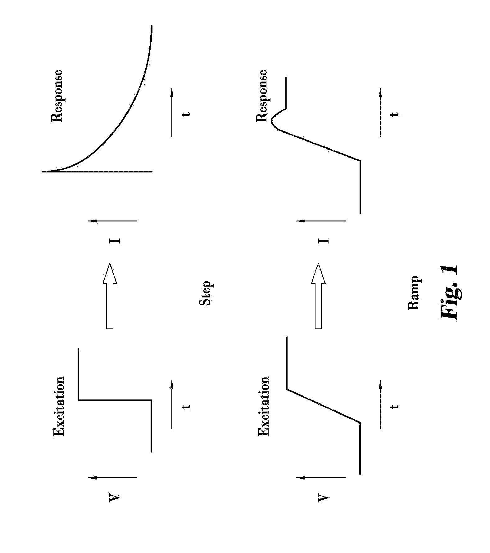
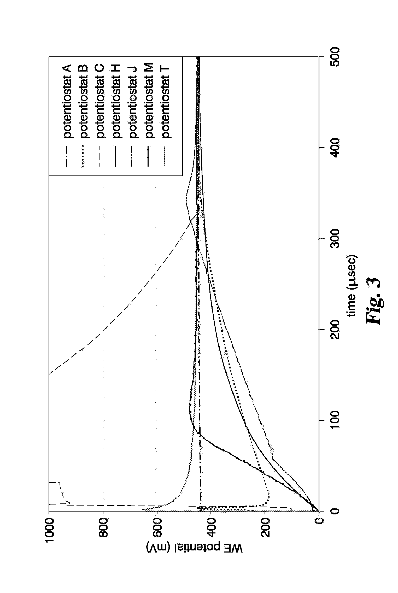
The invention helps to address the issue of variations in the measurement caused by the limitations of the meter system's slew rate capability. It uses a potentiostat's step excitation transition controlled at a slow enough pace that it is insensitive to changes in the sample, test strip, instrument electronics, and environmental conditions. The excitation potential is applied at a rate that is fast enough to minimize the impact on the current response and overall test time. This technique allows for easier replication of test results, sample insensitive, and more precise results at earlier times. In one embodiment, a 450 mV excitation potential is applied with a transition time greater than about 500 μsec. The invention helps to minimize the potentiostat's transient response requirements, reduce variations in the current response, and improve test result reproducibility.

Problems solved by technology

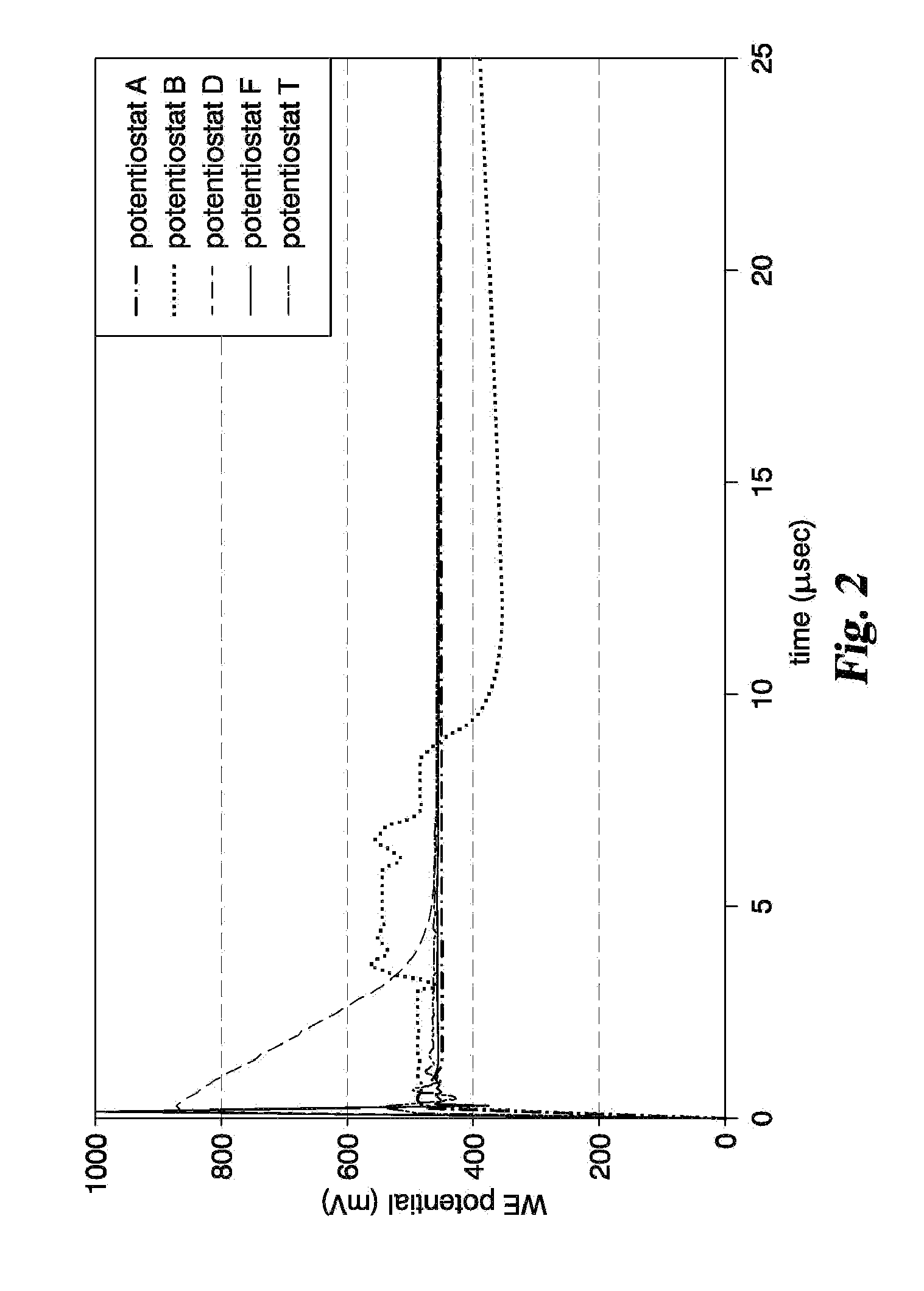
More particularly, it was found that an operational amplifier's potential step response with a capacitive load may create excitation instability, resulting in undesirable variation in the amperometric response, which makes the measurement inherently less precise.
In other words, limitations in slew rate capability of the meter system itself can give rise to undesirable effects in the amplifier.

Method used


Image

  • Controlled slew rate transition for electrochemical analysis
  • Controlled slew rate transition for electrochemical analysis
  • Controlled slew rate transition for electrochemical analysis

Examples


examples

[0053]The invention will be more fully understood upon consideration of the following non-limiting examples, which are offered for purposes of illustration, not limitation.

[0054]Turning now to FIG. 9, it shows a graph of the current response to the ramped-shaped, sinusoidal-shaped and exponential-shaped 550 mV excitation potentials with the 200 μsec transition time for a glucose linearity solution with a glucose concentration of about 400 mg / dl (LIN 4). Compared to the current response of the step excitation potential also illustrated in the graph of FIG. 9, the ramped-shaped, sinusoidal-shaped, and exponential-shaped excitation potentials (i.e., the ones with the controlled transition time) have a significantly lower peak current response, with the ramped-shaped excitation potential having the smallest peak current. This reduction of the peak current response continues as the transition time becomes longer. As shown in FIGS. 10 and 11, the peak current response becomes even lower w...


PUM

PropertyMeasurementUnit
resistanceaaaaaaaaaa
transition timeaaaaaaaaaa

Abstract

Measurement systems and methods are disclosed for minimizing the effects created by a meter's output amplifier during electrochemical measurements. In the systems and methods, transition of an excitation potential applied between electrodes of a test strip is controlled so that it is at a sufficiently slow rate below a slew rate capability of the system (but still fast enough to minimally impact overall test time) to reduce variability in the test results. The methods and systems therefore use a transition having a ramp-shaped waveform, a sinusoidal-shaped waveform or an exponential-shaped waveform. Additionally, the excitation potential can be purposefully controlled by a processor, memory driven digital-to-analog converter or external circuitry at a rate sufficiently slow to make variations in the analog electronics slew rate insignificant for all sample types and test conditions.

Description

CROSS-REFERENCE TO RELATED APPLICATIONS[0001]This patent application is a continuation of Int'l Patent Application No. PCT / EP2011 / 006342; filed 14 Dec. 2011, which claims the benefit of U.S. Provisional Patent Application No. 61 / 424,856; filed 20 Dec. 2010. Each patent application is incorporated herein by reference as if set forth in its entirety.TECHNICAL FIELD[0002]The invention relates generally to engineering and electrochemistry, and more particularly to systems and methods that minimize undesirable effects created by an electrochemical potentiostat's output amplifier during amperometric measurements.BACKGROUND[0003]Home monitoring of various biological conditions, such as diabetes, has become quite common in recent years. With the advent of home monitoring, there has been a need for the measurements to be accurate and precise. When controlling measurement precision, there are a number of possible sources for error, including the characteristics of the sample itself (e.g., hem...

Claims


Application Information

Patent Timeline
Patent Type & Authority Applications(United States)
IPC IPC(8): G01N27/48
CPCG01N27/48G01N27/3273
Inventor BEATY, TERRY A.
Owner ROCHE DIABETES CARE INC
Learn More