
Wind turbine measurement system

a measurement system and wind turbine technology, applied in the direction of propellers, fluid speed measurement using pressure difference, engine control parameters, etc., can solve the problems of inaccurate measurement of wind direction, wind turbines only operating efficiently, equipment cannot precisely measure wind direction, etc., to achieve the effect of responding more accurately to wind conditions

Active Publication Date: 2013-10-17
SIEMENS GAMESA RENEWABLE ENERGY AS
View PDF7 Cites 19 Cited by
  • Summary
  • Abstract
  • Description
  • Claims
  • Application Information

AI Technical Summary

Benefits of technology

The invention aims to improve the accuracy of response for wind turbine components controller by providing a way to consider wind conditions.

Problems solved by technology

A wind turbine can only operate efficiently if it can respond to the momentary wind conditions.
However, when using sensors placed on the nacelle, the measured wind data is inaccurate on account of the turbulence generated by the upwind rotor blades and their cyclic wind shadow.
Therefore, such equipment cannot measure the wind direction precisely, and cannot be used to generate a precise yaw angle.
Using the prior art system, therefore, it can never be precisely determined whether the spinner is facing directly into the wind.
Even a slight error in estimating the wind direction results in a corresponding “yaw angle error”, and the relatively inefficient positioning of the spinner and therefore also the rotor blades results in a less than optimal power output of the wind turbine.
A yaw angle error is not only a problem as regards energy output of the wind turbine.
Another problem is that components of the wind turbine such as bearings and the rotor blades can be subject to asymmetrical loading, so that failure as a result of material fatigue can become a problem, with ensuing maintenance and repair costs.
Of course, any measuring equipment located on the outside of the nacelle is also exposed to severe weather conditions, so that costly maintenance procedures are necessary here also.

Method used


Image

  • Wind turbine measurement system
  • Wind turbine measurement system
  • Wind turbine measurement system

Examples


Embodiment Construction

[0046]In the diagrams, like numbers refer to like objects throughout. Objects in the diagrams are not necessarily drawn to scale.

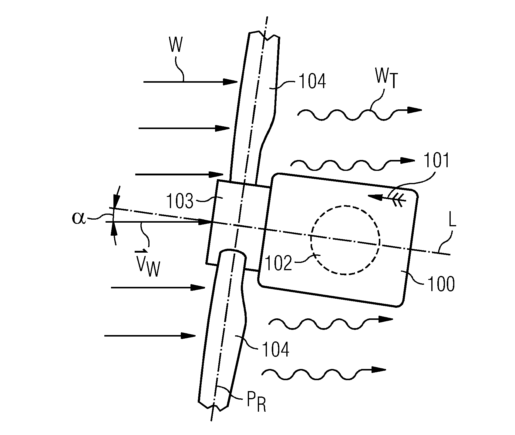
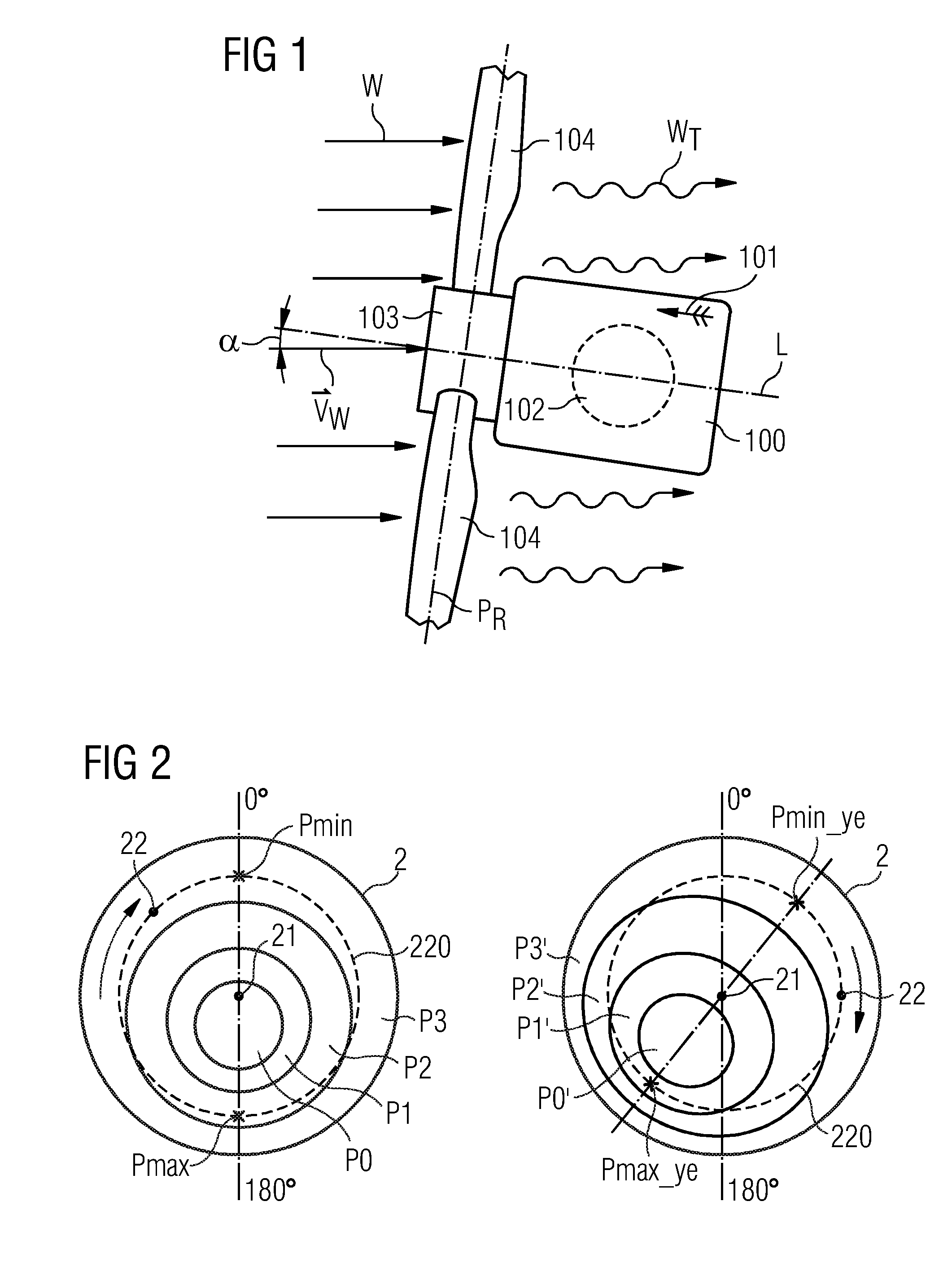
[0047]FIG. 1 shows a schematic representation of a plan view of a prior art wind turbine in a non-ideal position relative to the wind. Seen from above, a nacelle 100 can be rotated by a yaw drive 102 (indicated by the broken line) with the intention of bringing a longitudinal axis L of the nacelle 100 and spinner 104 into line with the momentary direction vW of the wind W. A controller of the yaw drive 102 acts in response to measurements delivered by a wind vane 101 mounted on the top of the nacelle 100. The rotor blades 104 describe a virtual “rotor disc” or “rotor plane” PR as they rotate, indicated here by the broken line (whereby the rotor plane PR is perpendicular to the plane of the drawing). Because the wind vane 101 is situated behind the rotor plane PR, and the rotor blades 104 cause a certain amount of turbulence WT behind the rotor plane, the m...


PUM


Abstract

A measurement system is provided for a wind turbine having a plurality of rotor blades mounted to a spinner at the front of a nacelle and arranged to rotate in a rotor plane. The measurement system includes a measuring device for determining a pressure at a number of pressure measurement points. The pressure measurement points are arranged in front of the rotor plane, an analysis module for generating a control signal on the basis of the pressure measurements, and output means for issuing the control signal to a controller of the wind turbine.

Description

CROSS REFERENCE TO RELATED APPLICATIONS[0001]The present application claims priority to European Patent Office application No. 12164472.8 EP filed Apr. 17, 2012, the entire content of which is hereby incorporated herein by reference.FIELD OF INVENTION[0002]The invention describes a measurement system for a wind turbine; a spinner for a wind turbine; a wind turbine comprising a measurement system; and a method of controlling a wind turbine.BACKGROUND OF INVENTION[0003]A wind turbine can only operate efficiently if it can respond to the momentary wind conditions. For example, maximum energy can only be extracted from the wind when the wind turbine is facing essentially directly into the wind. In this position, the wind turbine can extract the most kinetic energy from the wind and convert it into electrical energy. To this end, most wind turbines are equipped with a yaw drive, for example between the wind turbine nacelle and the tower, so that the nacelle, and therefore also the hub an...

Claims


Application Information

Patent Timeline
IPC IPC(8): F03D7/02
CPCF03D7/02F03D7/0264F03D7/0204G01P5/14F05B2270/30F05B2270/3015F05B2270/32F05B2270/329F05B2270/80F05B2270/802F03D80/00F03D17/00Y02E10/72
Inventor ANDERSEN, JIMMIJENSEN, JAN MARTIN
Owner SIEMENS GAMESA RENEWABLE ENERGY AS
Learn More