Flycutting groove machining method and flycutting mirror finishing method on film-like workpiece
- Summary
- Abstract
- Description
- Claims
- Application Information
AI Technical Summary
Benefits of technology
Problems solved by technology
Method used
Image
Examples
Embodiment Construction
[0022]Embodiments of the present invention will be described herebelow with reference to the attached drawings.
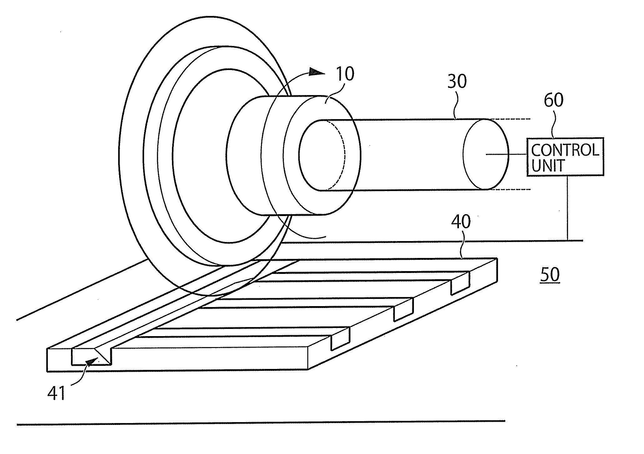
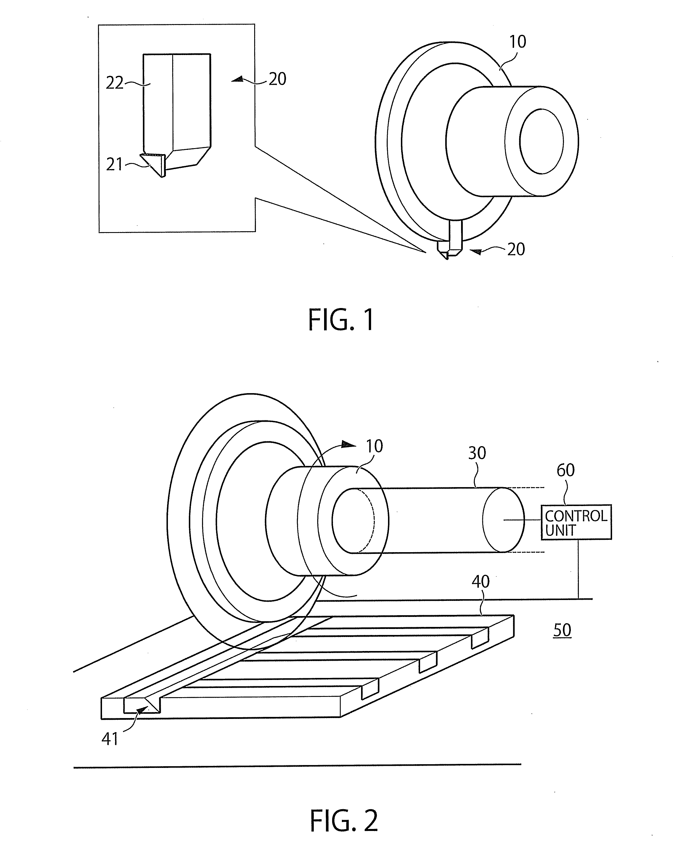
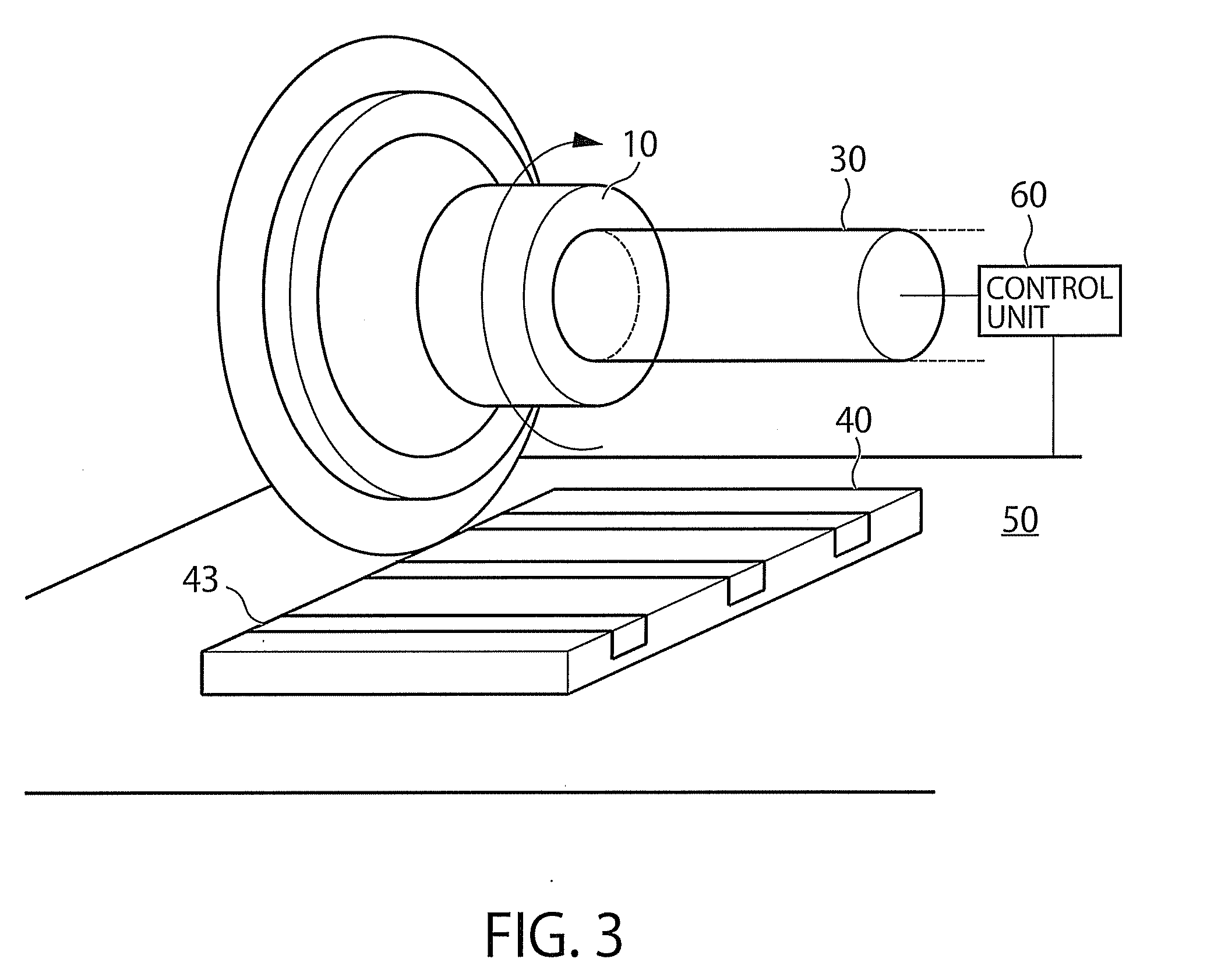
[0023]FIG. 1 is a schematic view showing a flycutting tool and a flycutting flange, for realizing a flycutting groove machining method on a film-like workpiece in one embodiment of the present invention. FIG. 2 is a schematic view for explaining the groove machining method.
[0024]As shown in FIG. 1, in this embodiment, a flycutting flange 10 is employed as a flycutting jig to be mounted on a rotary spindle. A flycutting tool 20 is mounted on the flycutting flange 10. The flycutting tool 20 is also referred to as “angled cutter”, and is composed of a monocrystal diamond tool 21 and a metal shank 22 in this embodiment. The monocrystal diamond tool 21 and the metal shank 22 are fixed to each other by brazing.
[0025]As shown in FIG. 1, the monocrystal diamond tool 21 in this embodiment is formed of a tool of a triangular type, with a distal end thereof having an angle of 45 degre...
PUM
| Property | Measurement | Unit |
|---|---|---|
| Area | aaaaa | aaaaa |
Abstract
Description
Claims
Application Information
 - R&D
- Intellectual Property
- Life Sciences
- Materials
- Tech Scout
- Unparalleled Data Quality
- Higher Quality Content
- 60% Fewer Hallucinations
Browse by: Latest US Patents, China's latest patents, Technical Efficacy Thesaurus, Application Domain, Technology Topic, Popular Technical Reports.
© 2025 PatSnap. All rights reserved.Legal|Privacy policy|Modern Slavery Act Transparency Statement|Sitemap|About US| Contact US: help@patsnap.com


