
Brillouin Optoelectronic Measurement Method and Apparatus

a technology of optoelectronic measurement and apparatus, applied in the direction of measurement device, converting sensor output, scattering property measurement, etc., can solve the problems of limiting the practicality of coding, limiting the application of coding, and not providing a satisfactory solution, so as to improve the signal to noise ratio, the effect of easy to distinguish from nois

Active Publication Date: 2013-10-10
OMNISENS
View PDF7 Cites 19 Cited by
  • Summary
  • Abstract
  • Description
  • Claims
  • Application Information

AI Technical Summary

Benefits of technology

The optoelectronic measurement method described in this patent uses a pump signal that is time-frequency coded, which makes it easier to distinguish from noise and achieve a higher signal to noise ratio. This results in improved spatial resolution and allows for measuring temperature or strain conditions over a longer distance with reduced drifts in measurement. The method also takes advantage of the natural symmetry in the coding matrix to minimize noise after decoding. Overall, this method provides improved accuracy and efficiency in optical measurement.

Problems solved by technology

Most of the proposed solutions are not satisfactory since they require a complex remotely powered hardware that is not an attractive solution.
The implementation of such a coding requires no modification of the hardware of the device, just a change in the software driving the device and a substantial overhead in calculations, so that it can be seen like an upgrade at a very low added cost.
However, SIMPLEX code is efficient if it is composed by “return to zero” (RZ) signals, which are more difficult to manage than “non return to zero” (NRZ) signals which limits its practicality.
However, such coding does not provide a satisfactory solution as the signal to noise ratio of the acquired signals is still not significantly increased.
Accordingly, the spatial resolution and the accuracy of the performed measurements of temperature and deformation is still significantly compromised.
Therefore, in view of the above description, the problem of having available an optoelectronic measuring method and apparatus, which is used to measure contemporaneously the change over time both of the local temperature and of the local strain of an engineering or architectonical structure, is currently solved in a dissatisfactory manner and represents an interesting challenge for the Applicant, which has the object of providing a measuring apparatus, which is at the same time efficient, economical and reliable.

Method used


Image

  • Brillouin Optoelectronic Measurement Method and Apparatus
  • Brillouin Optoelectronic Measurement Method and Apparatus
  • Brillouin Optoelectronic Measurement Method and Apparatus

Examples


Embodiment Construction

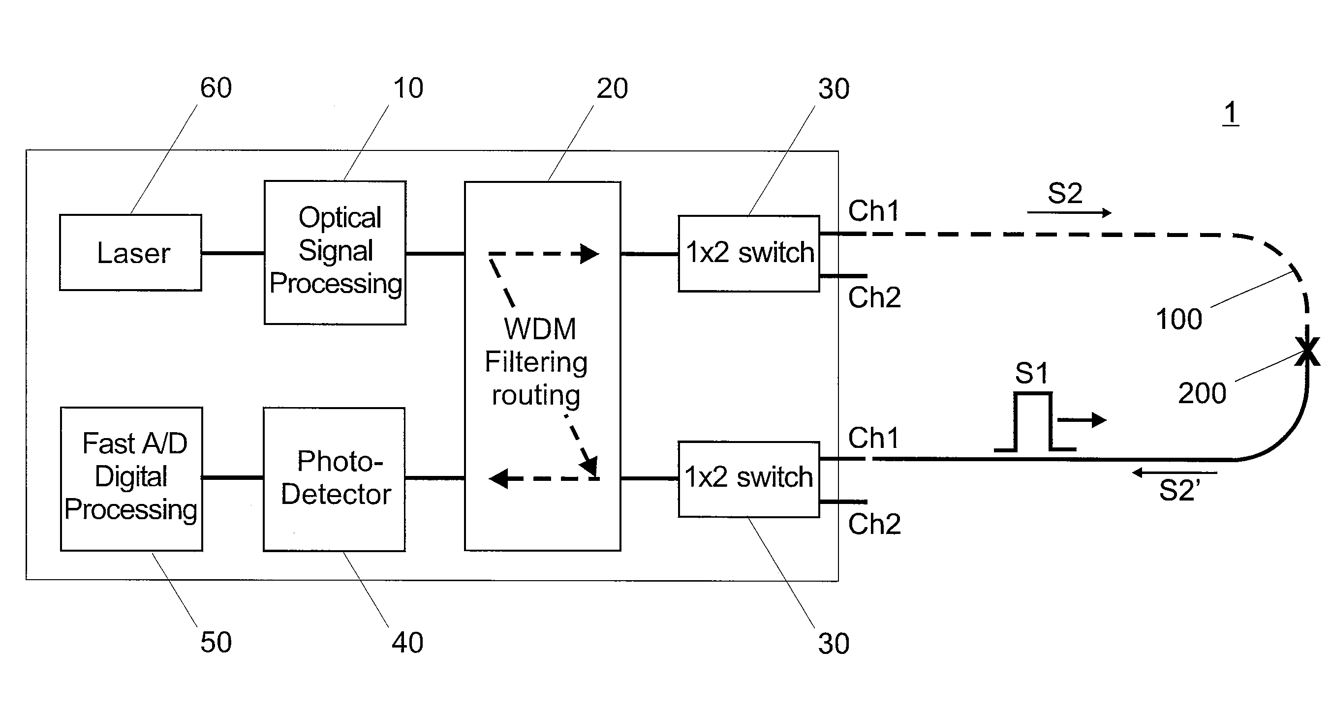
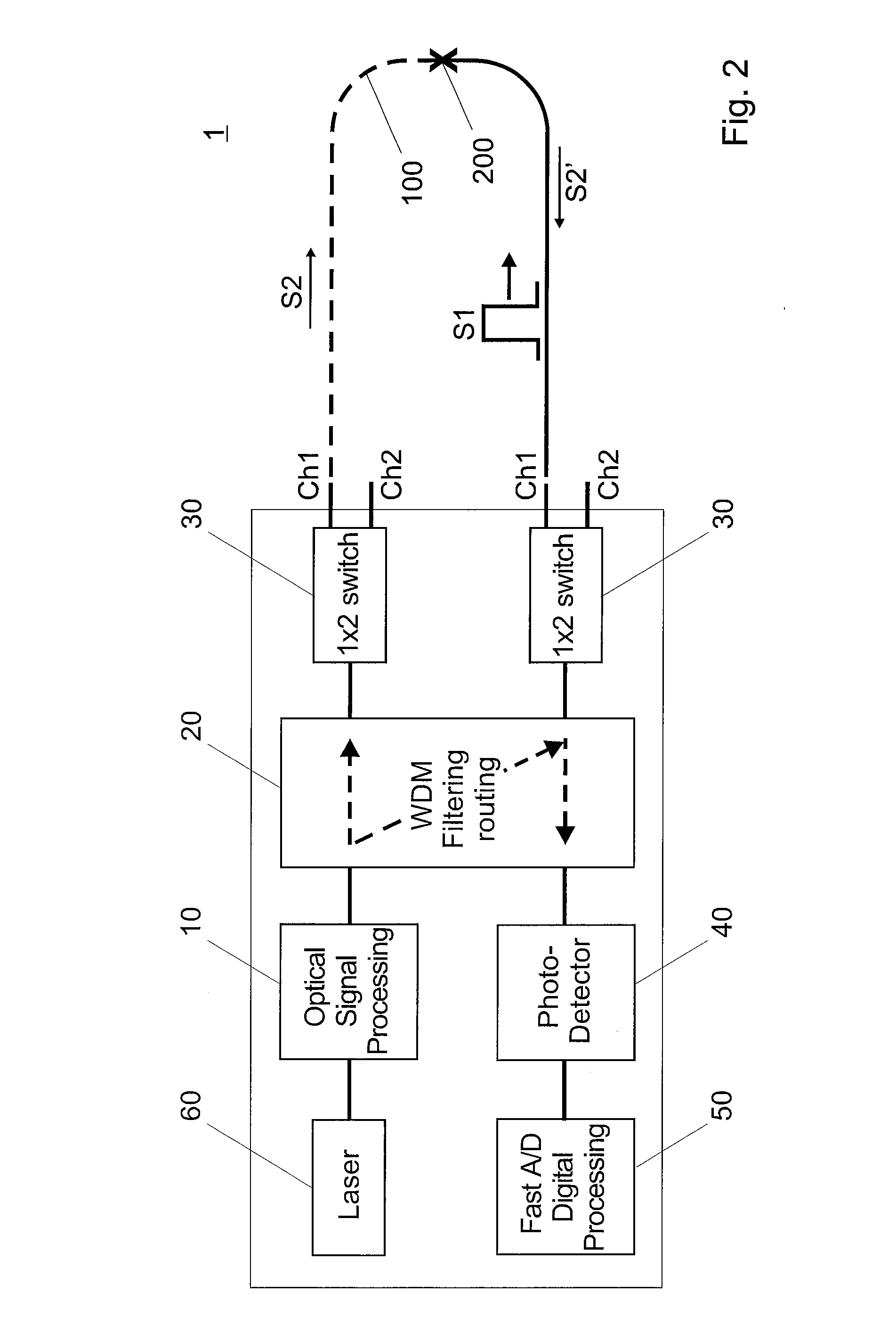
[0075]FIG. 2 is a schematic illustrating an optical fibre 100 in which the optoelectronic measurement method, according to the present invention, is carried out by using an optoelectronic measurement device 1 according to the present invention.

[0076]FIG. 2 refers to BOTDA. However the method and device according to the invention are not limited to BOTDA, but can apply also to BOTDR and in general to any optical system based on a Brillouin effect.

[0077]The device 1 comprises an optical source, e.g. a laser, operating at a determined wavelength, e.g. at 1550 nm. It is followed by an optical signal processing 10, arranged to generate the first signal s1, or pump, which is time-frequency coded and the second signal s2, or probe. In another embodiment two optical sources, e.g. two lasers, generate separately s1 and s2.

[0078]A Wavelength Division Multiplexing (WDM) filter 20 separates s1 and s2. In a preferred embodiment two 1×N switches 30 can manage N channels, where N is an integer num...


PUM

PropertyMeasurementUnit
Brillouin frequency shiftaaaaaaaaaa
Brillouin optoelectronic measurementaaaaaaaaaa
frequencyaaaaaaaaaa

Abstract

The present invention relates to a Brillouin optoelectronic measurement method comprising the step of, providing a signal (s1) in an optical fibre (100), wherein said signal (s1) is time-frequency coded. The present invention further relates to a corresponding device for use in such a method.

Description

FIELD OF THE INVENTION[0001]The present invention relates to an optoelectronic measurement method and device. In particular, but not exclusively, the present invention relates to an optoelectronic measurement method and device which can be used to monitor physical characteristics of an engineering structure.DESCRIPTION OF RELATED ART[0002]In many fields of application, like pipeline, power cables or subsea, the use of measuring apparatuses to monitor continuously structural and / or functional parameters is well known. The measuring apparatuses can be applied also to the civil engineering sector, and in particular in the field of the construction of structures of great dimensions.[0003]The measuring apparatuses are commonly used to control the trend over time of the temperature or of the strain, i.e. of the geometrical measure of the deformation or elongation resulting from stresses and defining the amount of stretch or compression along the fibre, of the respective structure. In more...

Claims


Application Information

Patent Timeline
Patent Type & Authority Applications(United States)
IPC IPC(8): G01N21/47
CPCG01D5/35364G01N21/47G01L1/242
Inventor LE FLOCH, SEBASTIEN
Owner OMNISENS
Learn More