Light-reflective anisotropic conductive adhesive and light-emitting device
a technology of anisotropic conductive adhesives and light-emitting devices, which is applied in the direction of non-metal conductors, conductors, metal/alloy conductors, etc., can solve the problems of increased production costs, increased cost, and difficulty in improving the light emission efficiency (light extraction efficiency) of light emitted from light-emitting elements, so as to reduce conduction reliability, increase production costs, and improve light emission efficiency
Inactive Publication Date: 2013-10-10
DEXERIALS CORP
View PDF6 Cites 22 Cited by
- Summary
- Abstract
- Description
- Claims
- Application Information
AI Technical Summary
Benefits of technology
The present invention pertains to a light-reflective anisotropic conductive adhesive (also known as an "insulating adhesive") which improves light emission efficiency without adding to production costs. The adhesive comprises a thermosetting resin composition with a certain amount of light-reflective needle-shaped insulating particles and light-reflective spherical insulating particles mixed together in a specific ratio. The resulting adhesive allows for improved light emission efficiency without the need for a separate light reflecting layer on the LED element. It also helps prevent cracks and conduction reliability issues that might arise when the temperature of the surroundings changes.
Problems solved by technology
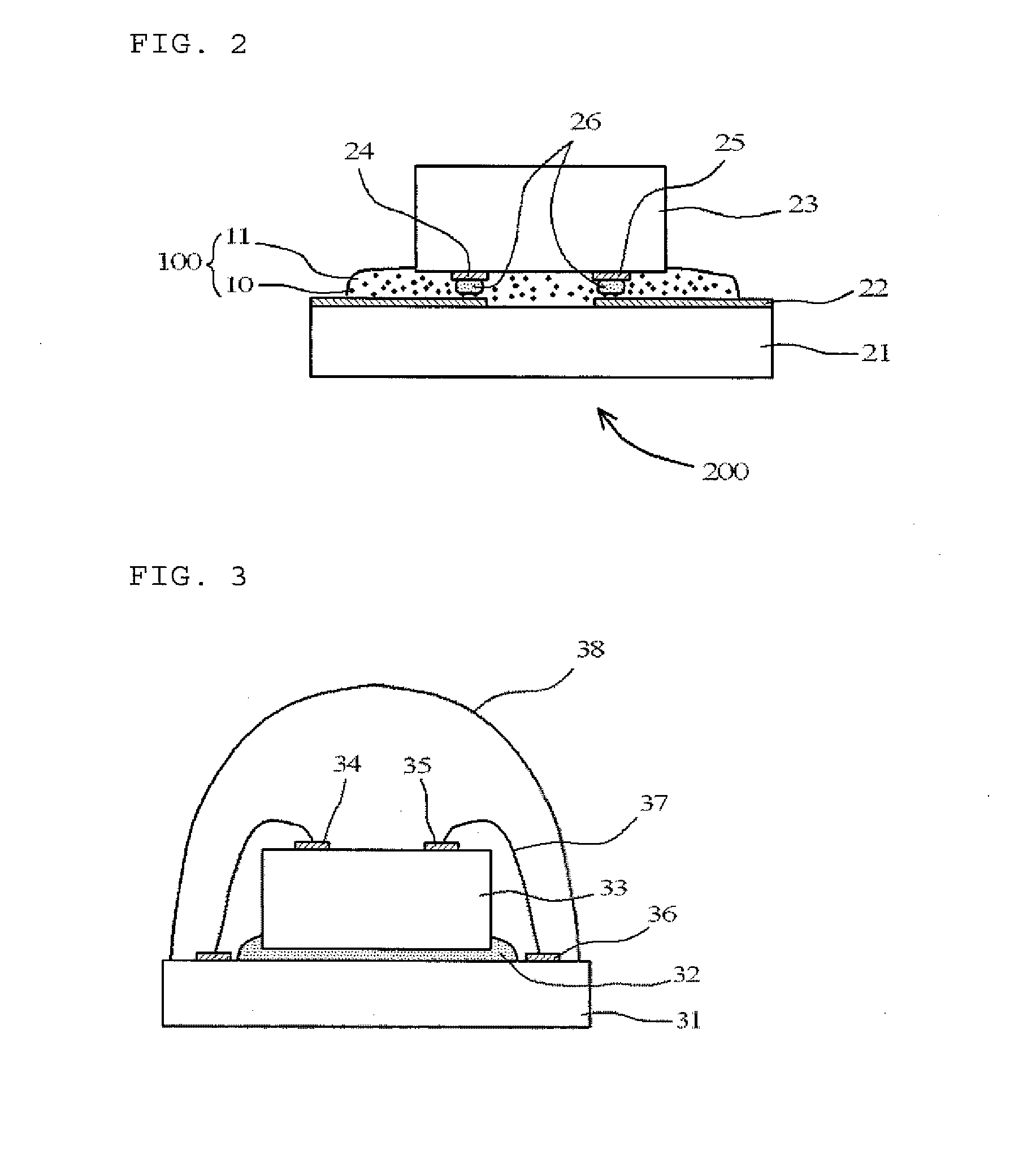
However, in the technology of Patent Literature 1, the light reflecting layer 40 must be provided on the LED element 33 by a metal vapor deposition method or the like so that the p electrode 34 and the n electrode 35 are insulated from each other, and therefore, there is a problem in that an increase in production cost is unavoidable.
Therefore, there is a problem in that it is difficult to improve the light emission efficiency (light extraction efficiency) of light emitted from the light-emitting element.
In addition to the above-described problems (the problem of an increase in cost and the problem of light extraction efficiency), there are more serious problems which are the occurrence of cracks in the anisotropic conductive connection portion and a reduction in conduction reliability.
This causes a problem in that cracks occur in the anisotropic conductive connection portion and a problem in that conduction reliability is reduced.
Method used
View moreImage
Smart ImageViewing Examples
Examples
examples
[0069]Specific examples of the present invention will next be described. However, the scope of the present invention is not limited to any of the following Examples.
Login to View More PUM
| Property | Measurement | Unit |
|---|---|---|
| aspect ratio | aaaaa | aaaaa |
| diameter | aaaaa | aaaaa |
| wavelength | aaaaa | aaaaa |
Abstract
A light-reflective anisotropic conductive adhesive used for anisotropic conductive connection of a light-emitting element to a wiring board contains a thermosetting resin composition, conductive particles, light-reflective needle-shaped insulating particles, and light-reflective spherical insulating particles. Each of the amount of the light-reflective needle-shaped insulating particles and the amount of the light-reflective spherical insulating particles in the thermosetting resin composition is 1 to 50 percent by volume based on the volume of the thermosetting resin composition, and the mixing ratio (V / V) of the light-reflective spherical insulating particles to the light-reflective needle-shaped insulating particles is 1:1 to 10. The light-reflective needle-shaped insulating particles are titanium oxide whiskers, zinc oxide whiskers, titanate whiskers, aluminum borate whiskers, or wollastonite.
Description
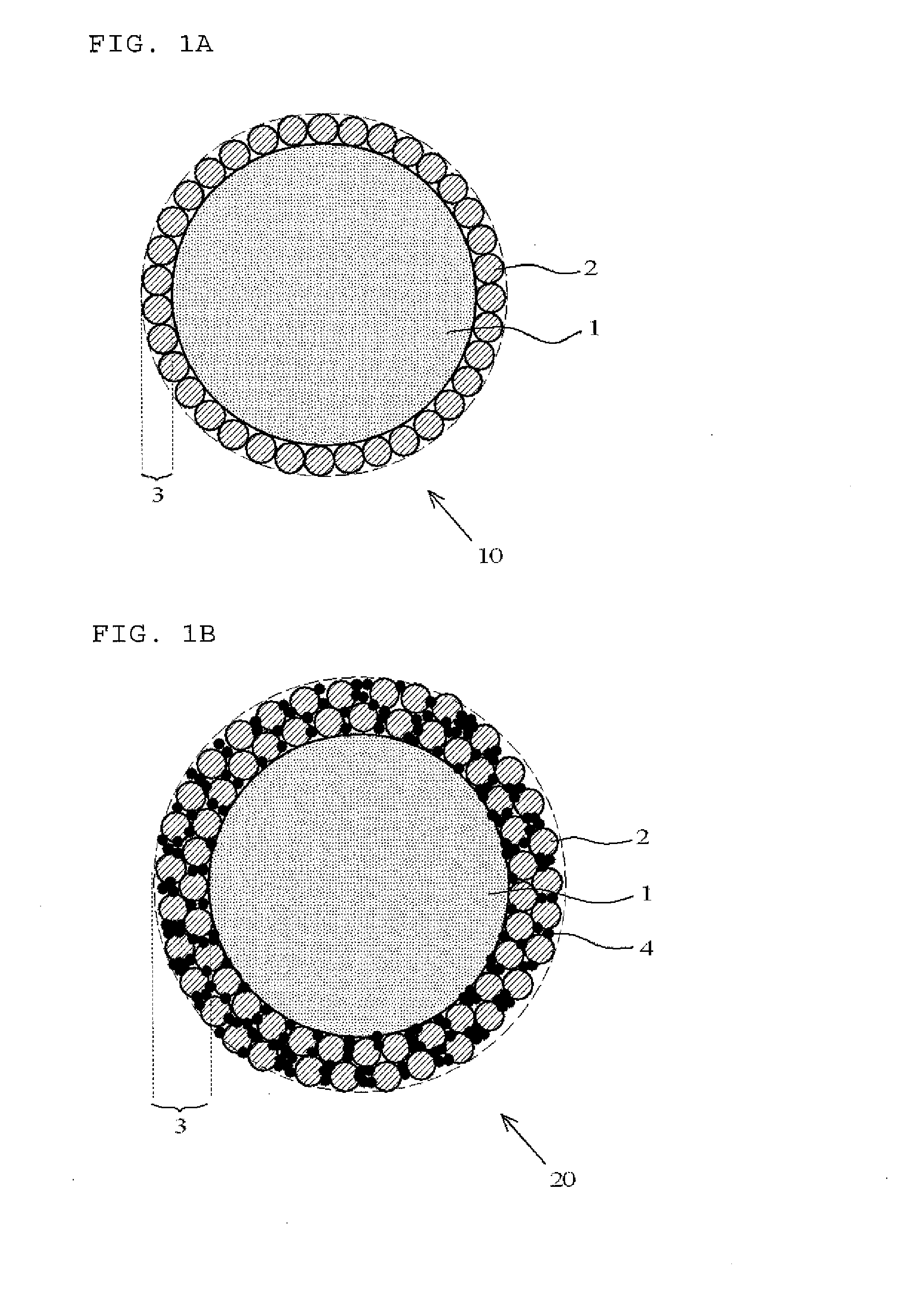
TECHNICAL FIELD[0001]The present invention relates to a light-reflective anisotropic conductive adhesive used for anisotropic conductive connection of a light-emitting element to a wiring board and also relates to a light-emitting device produced by mounting a light-emitting element on a wiring board using the adhesive.BACKGROUND ART[0002]Light-emitting devices using light-emitting diode (LED) elements are being widely used. An old-type light-emitting device has a structure shown in FIG. 3. More specifically, an LED element 33 is bonded to a substrate 31 with a die-bonding adhesive 32, and a p electrode 34 and an n electrode 35 on the upper surface of the LED element 33 are wire-bonded to connection terminals 36 of the substrate 31 with gold wires 37. The entire LED element 33 is sealed with a transparent molding resin 38. Incidentally, in the light-emitting device shown in FIG. 3, light having a wavelength of 400 to 500 nm and emitted upward from the LED element 33 is absorbed by t...
Claims
Login to View More Application Information
Patent Timeline
 Patent Type & Authority Applications(United States)
IPC IPC(8): H01L33/60
CPCH01L33/60H01L2924/12041H01L24/32H01L2224/16227H01L2224/2929H01L2224/29344H01L2224/29347H01L2224/29355H01L2224/29386H01L2224/83851H01L2224/294H01L2224/2939C09J9/02H01L2224/81903H01L2224/9211H01L2224/16225H01L2924/07811H01L2224/45144H01L2924/01029H01L2224/73265H01L2224/73204H01L2224/48227H01L2224/32225H01L24/29H01L2924/3512H01L2924/00H01L2924/00015H01L2924/00012H01L2924/00014H01L2924/05341H01L2924/05432H01L2224/81H01L2224/83H01L2224/05568H01L2224/05573H01L2924/181H01L2224/05599H01L33/62
Inventor NAMIKI, HIDETSUGUKANISAWA, SHIYUKIUMAKOSHI, HIDEAKIISHIGAMI, AKIRA
Owner DEXERIALS CORP
- R&D Engineer
- R&D Manager
- IP Professional
- Industry Leading Data Capabilities
- Powerful AI technology
- Patent DNA Extraction
Learn More Browse by: Latest US Patents, China's latest patents, Technical Efficacy Thesaurus, Application Domain, Technology Topic, Popular Technical Reports.
© 2024 PatSnap. All rights reserved.Legal|Privacy policy|Modern Slavery Act Transparency Statement|Sitemap|About US| Contact US: help@patsnap.com


