
Machine and system for applying container carriers to containers

a container carrier and machine technology, applied in the field of machine and system for applying container carriers to containers, can solve the problems of requiring extraordinary force for the cans to loosen from the retainer device, the carrier cannot be re-used, and the further movement required a considerable amount of force to releas

Inactive Publication Date: 2013-10-10
BRITISH POLYTHENE
View PDF10 Cites 9 Cited by
  • Summary
  • Abstract
  • Description
  • Claims
  • Application Information

AI Technical Summary

Benefits of technology

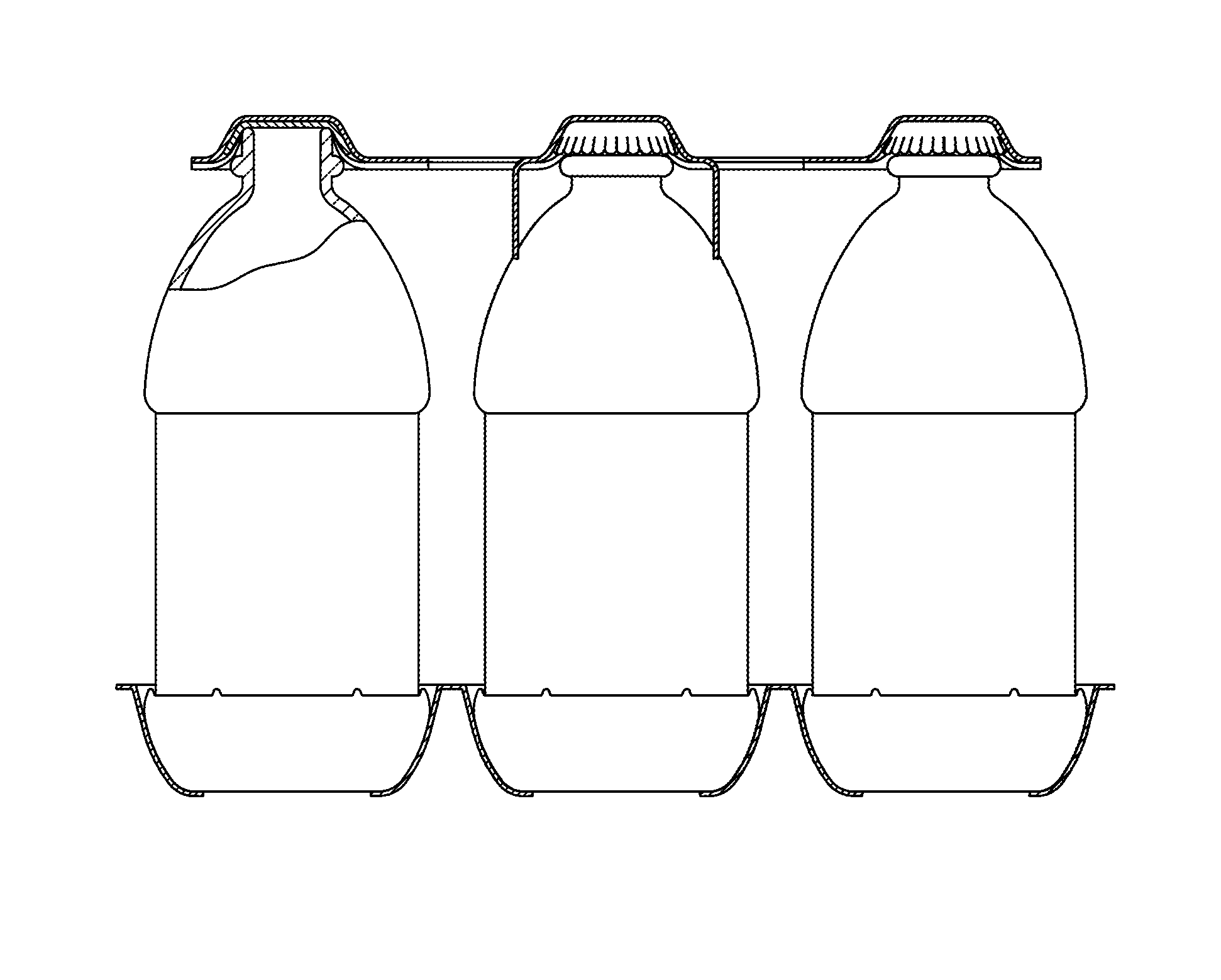
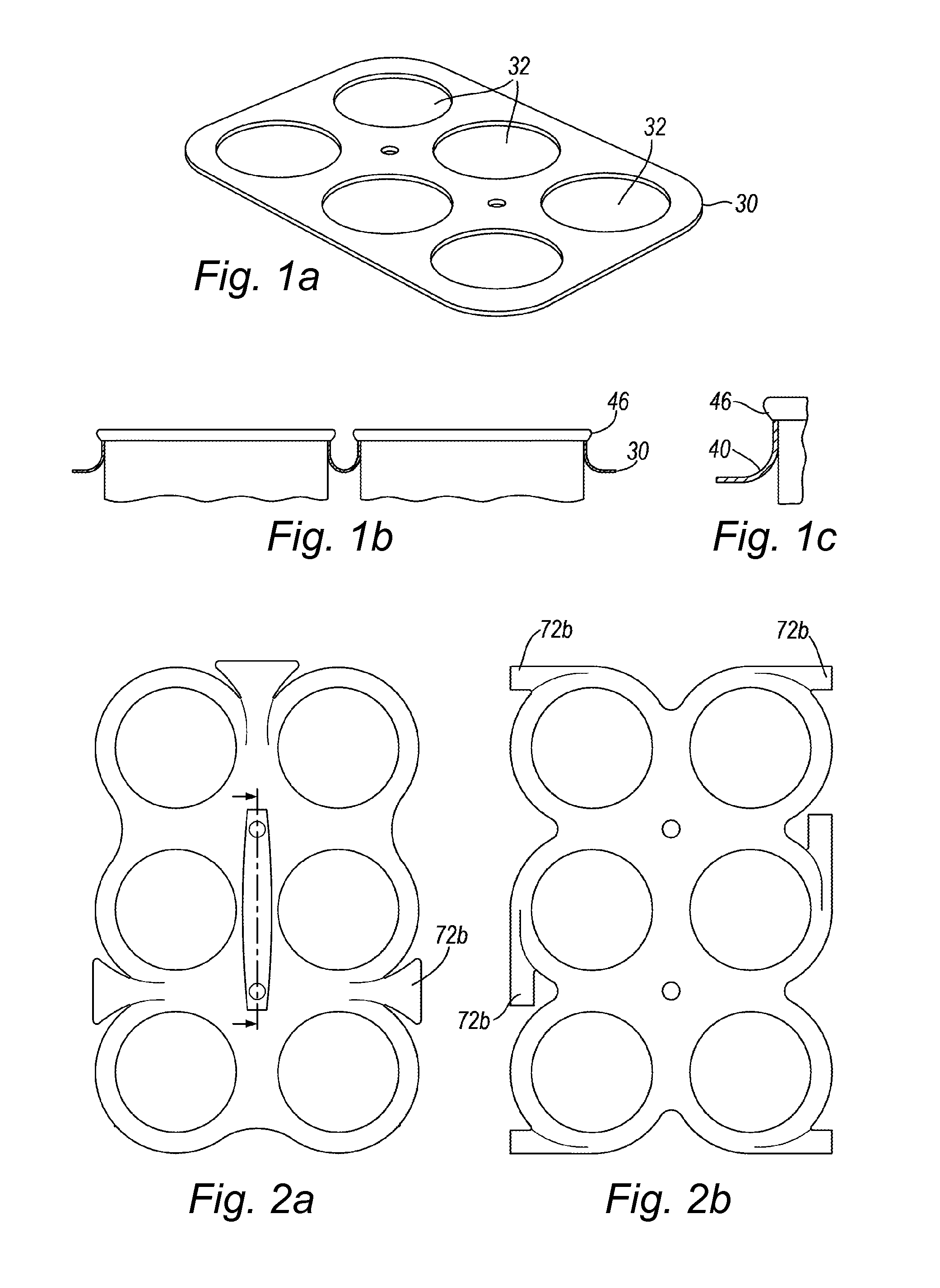
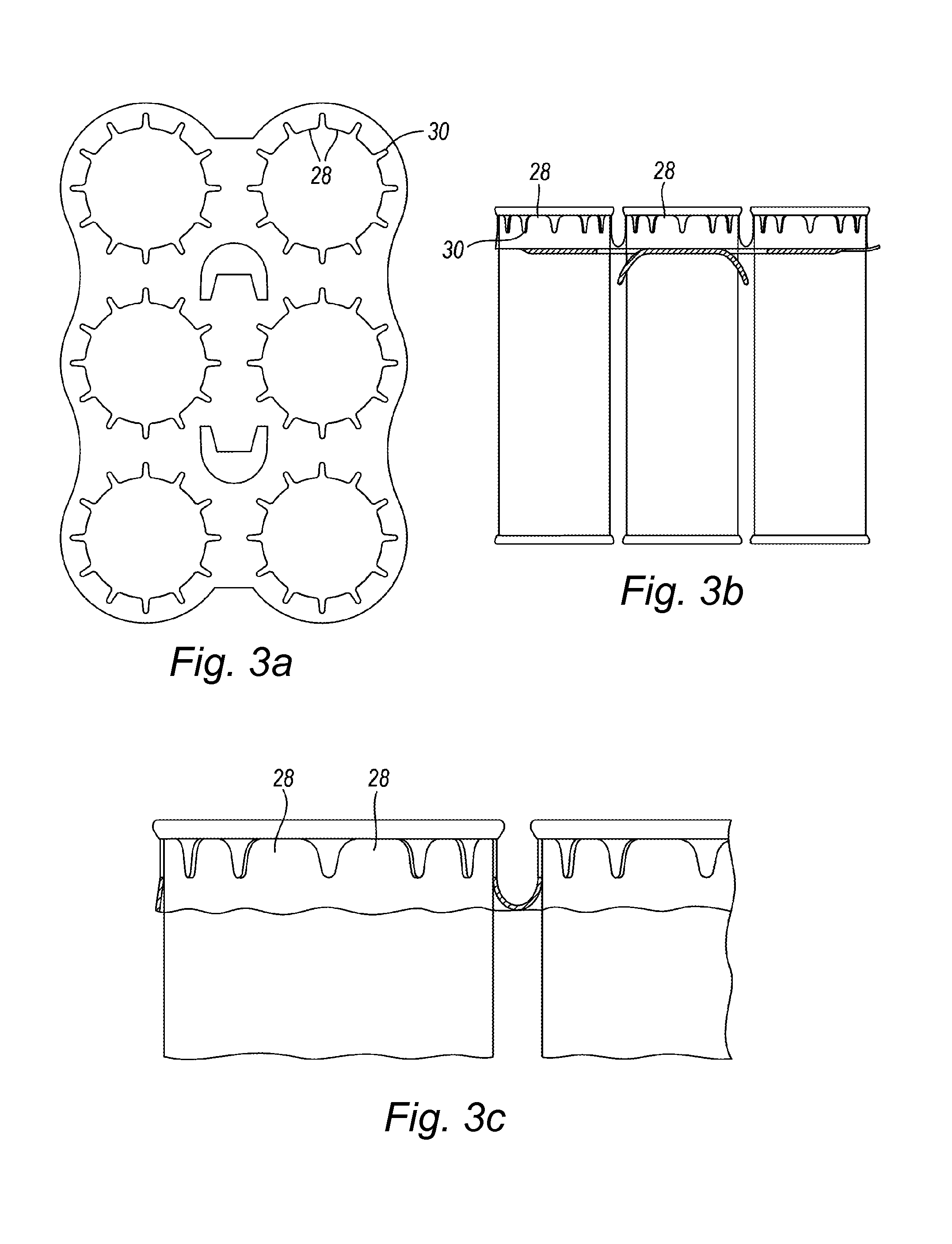
The present invention is about improving the connection between separate sheets of a plastic film used in packaging. The invention uses a thicker film with tabs or fingers that are designed to fit tightly around the edges of containers, such as beverage cans. The tabs are pushed downwards, creating a wave in the material that prevents the tabs from moving away from the can. This ensures a secure and strong connection between the film and the can. The thicker film also allows for a reduction in the required raw material and energy savings. Additionally, the invention allows for several packing streams to be placed in side-by-side configuration, enabling the manufacturing of larger packs. The invention takes advantage of the physical properties of the plastic film material, providing a stronger and more stable connection to the container.

Problems solved by technology

Such early forms of carrier film allowed the cans to be pulled through—albeit with some difficulty—but a reverse movement of the can with respect to the carrier would mean that the plastics flange would abut the bead and further movement required a considerable force to release the can.
Indeed, U.S. Pat. No. 2,874,835 indicates that extraordinary force is required for the cans to come loose from the retainer device accidentally.
After a container is removed from the carrier, the carrier cannot be re-used due to the permanent stretching deformation during the application for packaging purposes.
The forces necessary to enable the plastics film to engage with the sides of a can were considerable and, of course, the large forces that were utilised to pack the containers together resulted in problems in a consumer accessing an individual can.
Indeed, the stamping forces would have been considerable.
It was found that such spacing is, for many purposes, insufficient since, in practice, the closely adjacent articles such as bottles or cans would rub against each other so that the respective surfaces may be scratched or otherwise defaced.
For example, it is common practice to apply a label or other decorative design by lithography or other means to beverage cans and such labelling would be damaged if the cans were permitted to rub together unduly such as when the package was subjected to continual motion or vibration during transport.
That is to say the cans are attached with two cans being in a side-by-side arrangement: the systems are limited in use and generally could not reliably operate to provide cans packed, for example in 3×3 or 3×4 or 4×4 etc arrangements.
When the frusto-conical wall defines such a large angle relative to the can axis, it is difficult to apply carrier stock since the band segments defining the can receiving apertures have an undesirable tendency to slide up the cans and to rest on the cans above the lower edges of the chimes.
A further problem of known systems, where great forces have been used to apply the carrier stock, that they can be difficult to remove—not only by accident—in use, especially by youngsters, which has caused effervescent spillage to occur since the removal by force of a drinks can from a carrier strip has resulted in an unnecessary disturbance of the effervescent liquid inside, resulting in a spray or spillage upon a subsequent opening of the can.
These types of carrier stock have not, however, been widely adopted.

Method used


Image

  • Machine and system for applying container carriers to containers
  • Machine and system for applying container carriers to containers
  • Machine and system for applying container carriers to containers

Examples


Embodiment Construction

[0063]There will now be described, by way of example only, the best mode currently contemplated by the inventor for carrying out the present invention. In the following description, numerous specific details are set out in order to provide a complete understanding to the present invention. It will be apparent to those skilled in the art, that the present invention may be put into practice with variations of the specific.

Carrier Stock for Unitizing Containers

[0064]The present invention shall now be described with reference to a first embodiment as shown in FIGS. 8a-c. FIGS. 8a and 8b show first and second perspective views of an arrangement of five beer cans retained by plastics film stock having six container apertures.

[0065]The plastics film is shown in plan view in FIG. 8c. Each aperture 80a is of a general square shape, operably arranged to accept a circularly cylindrical part of a container therethrough, with four fingers or tabs 81, 82, 83&84 extending from indentations or trou...


PUM


Abstract

A container packaging system for containers applies an apertured plastics film carrier stock to substantially identical containers such as beverage cans having annular chimes, cylindrical side walls, and frusto-conical walls between the chimes and the side walls. The carrier stock has shaped apertures to securely retain drinks cans, food cans, bottles and similar containers, as a multi-pack unit. The carrier stock is rolled onto suitably juxtaposed containers engaging a tabbed aperture edge portion progressively from above to below the upper edge of the respective containers to be multi-packed and assumes a waveform 3D conformation to unitise the containers. The rolling method contrasts prior stretch application methods and enables cheaper and thinner carrier stock to be used.

Description

FIELD OF THE INVENTION[0001]The present invention relates to a method and system for applying container carriers to containers and to packaging systems for containers and using the same for packaging containers. This invention also pertains to a flexible carrier stock for machine application to substantially identical containers such as beverage cans having annular chimes, cylindrical side walls, and frusto-conical walls between the chimes and the side walls, and bottles with a neck ridge or seal beading. In particular, the present invention relates to the machine application of a plastics film having apertures to securely retain drinks cans, food cans, bottles and similar containers, a unique method of applying the film to the containers, the resultant combination providing a multi-package or unitised pack.BACKGROUND TO THE INVENTION[0002]It is common practice to package beverages such as sparkling fruit juices, cola drinks, beers and the like in cans, typically being manufactured ...

Claims


Application Information

Patent Timeline
IPC IPC(8): B65B17/02
CPCB65B17/025B65D71/504
Inventor BATES, STEPHEN PAUL
Owner BRITISH POLYTHENE
Learn More