
Methods and Systems for Predicting Cloud Movement

a cloud and cloud technology, applied in the field of solar energy, can solve the problems of limited power output of solar panels, difficult to predict cloud movement, and inability to detect distant low clouds

Inactive Publication Date: 2013-10-03
GENERAL ELECTRIC CO
View PDF5 Cites 38 Cited by
  • Summary
  • Abstract
  • Description
  • Claims
  • Application Information

AI Technical Summary

Benefits of technology

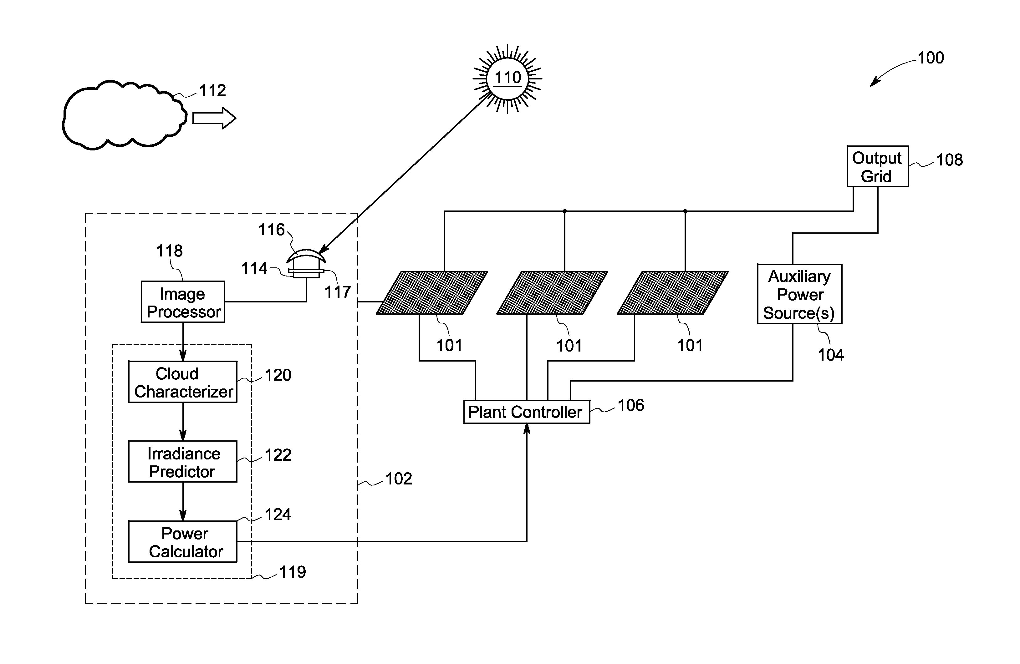
The patent presents a system and method for predicting solar irradiation based on the characteristics of clouds in the sky. A customized lens captures images of the sky, and an image processor analyzes those images to detect cloud patterns. A computing system then predicts the solar irradiation based on the detected cloud patterns. This system and method can help optimize the performance of solar panels in solar plants by providing accurate predictions of sunny or cloudy weather, and ultimately increasing the amount of sunlight that can be captured and converted into energy.

Problems solved by technology

For example, when a cloud's shadow falls on the solar panels, the shadow may partially or completely block sunlight, thereby limiting the power output of the solar panels.
The prediction of cloud movement, however, is technically challenging.
By way of example, since the sky typically spans over a wide angle of view, the movement of distant low clouds may not be easily detected.
For instance, it may be difficult to calculate the velocity, size, and orientation of clouds near the horizon.
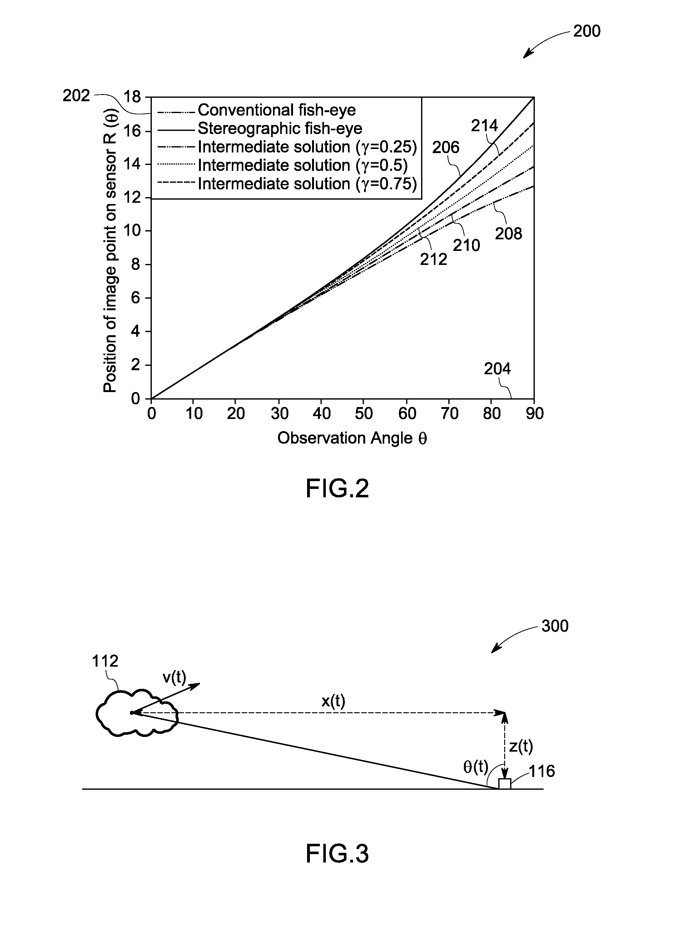
These wide-angle lenses, however, fail to accurately detect cloud movement of low-lying and fast-moving clouds at the circumference of the lens and therefore may not be able to effectively capture cloud movement.
If these auxiliary sources do not reach steady state before the occlusion event, the power output of the solar plant may disadvantageously fall below a threshold value.
Consequently, cloud movement and other characteristics are not easily discernible when the cloud is near the horizon.
Waiting for the cloud to reach the center of the lens, where the cloud movement and other characteristics are easily discernible, results in a delay in the computation of power output.
Accordingly, there may be a delay in energizing an auxiliary source and allowing the auxiliary source to reach steady state, thereby reducing the power output of the solar plant.

Method used


Image

  • Methods and Systems for Predicting Cloud Movement
  • Methods and Systems for Predicting Cloud Movement
  • Methods and Systems for Predicting Cloud Movement

Examples


Embodiment Construction

[0015]Embodiments of the present disclosure are related to systems and methods for predicting / estimating cloud movement using optimized optics. It will be noted that throughout this disclosure the terms ‘predict’ and ‘estimate’ have been interchangeably used. Further, as used herein, the term ‘irradiance’ refers to the density of solar terrestrial radiation incident on a given surface. The irradiance is typically expressed in watts per square centimeter or square meter.

[0016]Moreover, embodiments of the present disclosure are described with respect to predicting solar irradiance for a solar plant in case of occlusion events. The term ‘occlusion event’, as used herein, refers to events or duration of time for which a cloud cover shades one or more solar panels in the solar plant. It will be understood that the systems and methods to predict cloud movement described herein may be utilized in other applications as well. For example, these systems may be utilized in meteorological cente...


PUM


Abstract

A prediction system for predicting solar irradiance based on cloud characteristics is presented. The system includes a sky imager that includes a customized lens configured to capture one or more substantially planar images of the sky. The prediction system further includes an image processor coupled to the sky imager and configured to process the one or more substantially planar images. Moreover, the prediction system includes a computing system coupled to the image processor and configured to detect cloud characteristics based on the one or more substantially planar images, and predict the solar irradiance based on the cloud characteristics. Methods and non-transitory computer readable medium configured to perform the method for predicting power output of one or more solar panels in a solar plant based on cloud characteristics are also presented.

Description

BACKGROUND[0001]Embodiments of the present disclosure relate to solar energy, and more particularly to measurement, calculation, and prediction of cloud characteristics such as cloud movement.[0002]Images of the sky, commonly referred to as ‘sky images,’ are employed in diverse applications. For example, astronomers utilize sky images for analyzing cosmic movements and meteorological departments use these images to predict local weather conditions. Similarly, in one application, sky images may be utilized to observe the sun and clouds and to predict cloud cover, cloud movement over a given period, and solar radiation received at a particular location over a given time period. Determination of such cloud characteristics and solar irradiance may be employed in solar plants (employing solar panels or photovoltaic power grids) to ascertain or predict power output of the grid for particular time intervals and to control the grid output based on cloud movement. For example, when a cloud's...

Claims


Application Information

Patent Timeline
Patent Type & Authority Applications(United States)
IPC IPC(8): H04N13/02H04N7/18
CPCH04N7/18H04N13/0203F24J2/40H01L31/02021F24J2200/04Y02E10/40Y02E10/50G01W1/10F24S50/00F24S2201/00H04N13/204
Inventor SCHMIDT, MICHAELHELLER, CHRISTIAN MARIA ANTONMAYER, OLIVER GERHARDZETTL, MARCUSGONZALEZ, OMAR IVAN STERNHERNANDEZ, YARU NAJEM MENDEZLYNASS, MARK RONALDSERRA, EVA BERNALHARTUNG, MARIANNE
Owner GENERAL ELECTRIC CO
Learn More