
Facial image recognition apparatus

a facial image and recognition apparatus technology, applied in the field of facial image recognition apparatus, can solve the problems of increasing the cost of the device, deteriorating the recognition rate, and increasing the complexity of the device, and achieve the effect of high accuracy facial image recognition

Inactive Publication Date: 2005-04-19
KK TOSHIBA
View PDF17 Cites 98 Cited by
  • Summary
  • Abstract
  • Description
  • Claims
  • Application Information

AI Technical Summary

Benefits of technology

[0019]It is an object of the present invention to provide a facial image recognition apparatus and a pass control apparatus by which deterioration in the recognition rate due to illumination fluctuation in a ceiling illumination or the like can be reduced so that a high accuracy facial image recognition becomes possible.
[0020]It is an object of the present invention to provide a facial image recognition apparatus and a pass control apparatus by which deterioration in the recognition rate due to a difference in the angle of a light radiating illumination to the face of a human recognition object or the size of a facial image can be reduced so that a high accuracy facial image recognition becomes possible.
[0021]It is an object of the present invention to provide a facial image recognition apparatus and a pass control apparatus by which acquisition of a facial image becomes easy regardless of the height of a human recognition object, and a facial image of a state wherein a human recognition object stands still which is conventionally difficult to be acquired merely by one camera can be easily acquired.
[0022]It is an object of the present invention to provide a facial image recognition apparatus and a pass control apparatus by which the influence of the outer light due to solar light can be eliminated and the influence of the outer light due to an indoor illumination lamp can be eliminated.

Problems solved by technology

With respect to conventional facial image recognition apparatuses, recognition rates are deteriorated in some cases when the facial image of a human recognition object is photographed under the influence of outer light such as indoor illumination and solar light.
Thus, since it is necessary to newly provide a control circuit for controlling the quantity of light or a drive circuit for driving a lighting apparatus in the technique disclosed in Jpn. Pat. Appln. KOKAI Publication No. 11-316836, there is a problem that the device becomes complex and the cost of the device is increased.
However, in the technique disclosed in Jpn. Pat. Appln. KOKAI Publication No. 11-175718, since it is necessary to update registered information at the time of a change in an illumination condition, there is a problem that an encumbrance for a user increases.
Consequently, there is a problem that convenience for a user is deteriorated.
Thus, there is a problem that the structure of the apparatus becomes complex or the cost of the apparatus increases.
In some cases in conventional facial image recognition apparatuses, the recognition rates are deteriorated when photographing conditions such as distance and direction of a person are not constant.
Further, in the technique disclosed in Jpn. Pat. Appln. KOKAI Publication No. 10-134188, needed is a means selecting one camera in whose visual field a facial image exists, whereby a problem arises that the apparatus structure becomes very complex.
However, in the technique disclosed in Jpn. Pat. Appln. KOKAI Publication No. 7-312711, since it is assumed that a facial image is obtained while movement is made without encumbering a person, following problems arise.
Thus, in the technique disclosed in Jpn. Pat. Appln. KOKAI Publication No. 7-312711, processing at the time of registering a facial image becomes complex.
However, in the technique disclosed in Jpn. Pat. Appln. KOKAI Publication No. 7-312711, when face recognition is performed, in a case where a human recognition object is known in advance, the sight line guide only by the visual attention mark is difficult to be recognized.

Method used


Image

  • Facial image recognition apparatus
  • Facial image recognition apparatus
  • Facial image recognition apparatus

Examples


first embodiment

[0071]First, a first embodiment is explained.

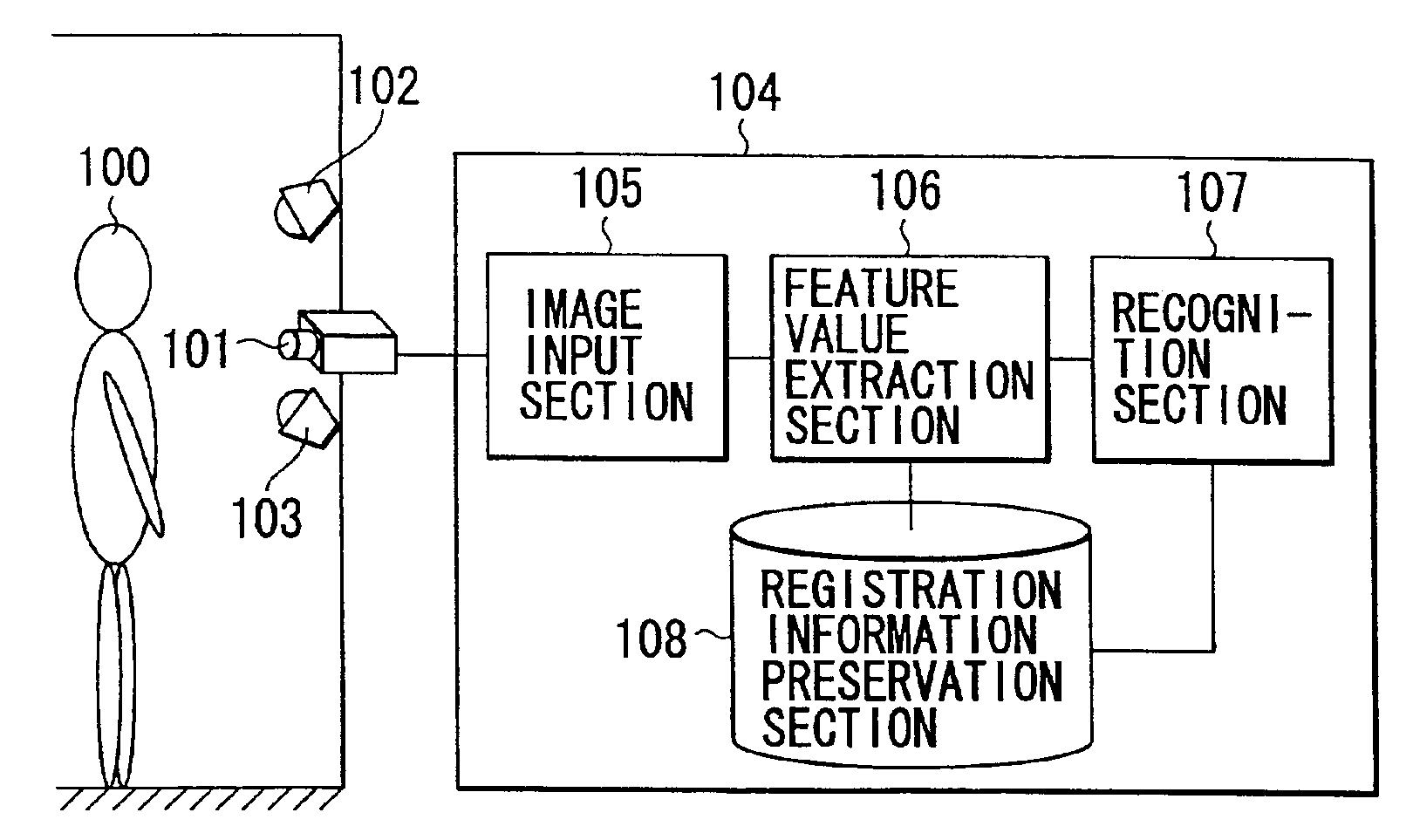
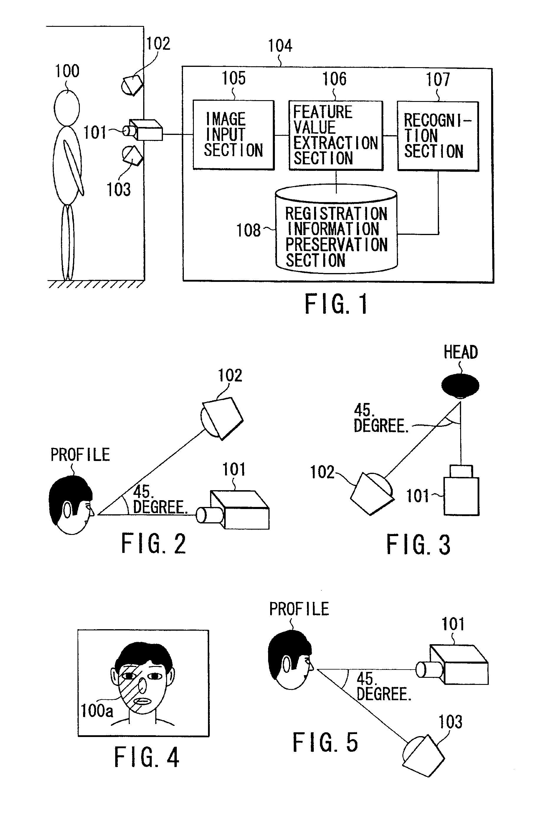
[0072]FIG. 1 schematically shows the structure of a facial image recognition apparatus according to the first embodiment of the present invention. This facial image recognition apparatus has a camera 101, a first illumination section 102, a second illumination section 103, and an image processing section 104.

[0073]The camera 101 photographs and inputs a facial image of a human recognition object 100. This camera 101 is the one photographing and inputting a facial image of the human recognition object 100. The camera 101 is composed, for example, of a television camera employing an image pickup element such as a CCD sensor.

[0074]The first illumination section (first illumination) 102 radiates light at a certain illuminance from a right upper part or a left upper part of the camera 101 to the face of the human recognition object 100. This first illumination section 102 is a lighting apparatus such as a fluorescent lamp radiating light at a ...

second embodiment

[0115]Next, a second embodiment is explained.

[0116]FIG. 8 schematically shows the structure of a facial image recognition apparatus according to the second embodiment of the present invention. This facial image recognition apparatus has a camera 101, a first illumination section 102, a second illumination section 103, an image processing section 104, and a light interruption section 109 as an outer light interruption means interrupting the light from a horizontal direction such as solar light.

[0117]The camera 101, the first illumination section 102, the second illumination section 103, and the image processing section 104 have the same structures as those of the first embodiment described above and have the same operations. Thus, explanation for the same structures as those of the first embodiment described above are omitted. The outer light interruption section 109 is explained below.

[0118]The outer light interruption section 109 interrupts the outer light radiated from a horizonta...

third embodiment

[0123]Next, a third embodiment is explained.

[0124]FIG. 11 schematically shows the structure of a facial image recognition apparatus according to the third embodiment of the present invention. This facial image recognition apparatus has a camera 101, a first illumination section 102, a second illumination section 103, an image processing section 104, and a display section 110 as a display means displaying a facial image of the human recognition object 100 photographed.

[0125]The camera 101, the first illumination section 102, the second illumination section 103, and the image processing section 104 have the same structures as those of the first embodiment described above and have the same operations. Thus, explanation about the same structures as those of the first embodiment described above are omitted, and the display section 110 is explained below.

[0126]FIG. 12 and FIG. 13 are drawings showing examples of facial images of a person displayed in the display section 110. FIG. 12 is a ...


PUM


Abstract

A first illumination section radiates light at a certain degree of illuminance toward the face of a human recognition object from an upper right part or an upper left part of a camera, and a second illumination section radiates light at a certain degree of illuminance toward the face of the human recognition object from a lower part of a camera. The camera photographs and inputs a facial image of the human recognition object. The image processing section extracts a feature value of the face of the human recognition object from a facial image inputted by the camera and collates the feature value extracted with a standard feature value registered in advance so as to recognize a facial image of the human recognition object.

Description

CROSS-REFERENCE TO RELATED APPLICATIONS[0001]This application is based upon and claims the benefit of priority from the prior Japanese Patent Applications No. 2000-080702, filed Mar. 22, 2000; No. 2000-080703, filed Mar. 22, 2000; and No. 2000-334977, filed Nov. 1, 2000, the entire contents of all of which are incorporated herein by reference.BACKGROUND OF THE INVENTION[0002]The present invention relates to a facial image recognition apparatus recognizing a facial image of a person, for example, in a security management or the like and a pass control apparatus controlling the pass of a passenger, employing this facial image recognition apparatus.[0003]With respect to conventional facial image recognition apparatuses, recognition rates are deteriorated in some cases when the facial image of a human recognition object is photographed under the influence of outer light such as indoor illumination and solar light. In order to reduce such deterioration in the recognition rate due to the ...

Claims


Application Information

Patent Timeline
IPC IPC(8): G06K9/00G07C9/00
CPCG06K9/00228G07C9/00079G07C9/00158G07C9/00111G07C9/00103G07C9/253G07C9/28G07C9/27G07C9/37G06V40/161
Inventor DOBASHI, HIRONORIHIRASAWA, TOSHIOOKAZAKI, AKIOSATO, TOSHIOSUKEGAWA, HIROSHI
Owner KK TOSHIBA
Learn More