Fuel injection valve

a technology of fuel injection valve and fuel injection chamber, which is applied in the direction of magnets, machines/engines, magnets, etc., can solve the problems of inability to manufacture while maintaining the highest functionality, and the outside diameter is extremely small, and achieves the highest functionality, compact construction, and small diameter

Active Publication Date: 2013-10-03
ROBERT BOSCH GMBH
View PDF8 Cites 5 Cited by
  • Summary
  • Abstract
  • Description
  • Claims
  • Application Information

AI Technical Summary

Benefits of technology

The present invention provides a fuel injector that has a small size and can be flexibly mounted in different vehicles without changes in the size of the valve needle or sleeve. The fuel injector has a high dynamic range of operation and can be used with various magnetic separation or choke configurations. The technical effect of the invention is to provide a compact fuel injector that can be easily installed and has improved performance.

Problems solved by technology

The valve has an extremely small outside diameter, such as for the technical world in the field of manifold injectors for internal combustion engines, until now, seemed to be impossible to manufacture while maintaining the highest functionality.

Method used


Image

  • Fuel injection valve
  • Fuel injection valve
  • Fuel injection valve

Examples


Embodiment Construction

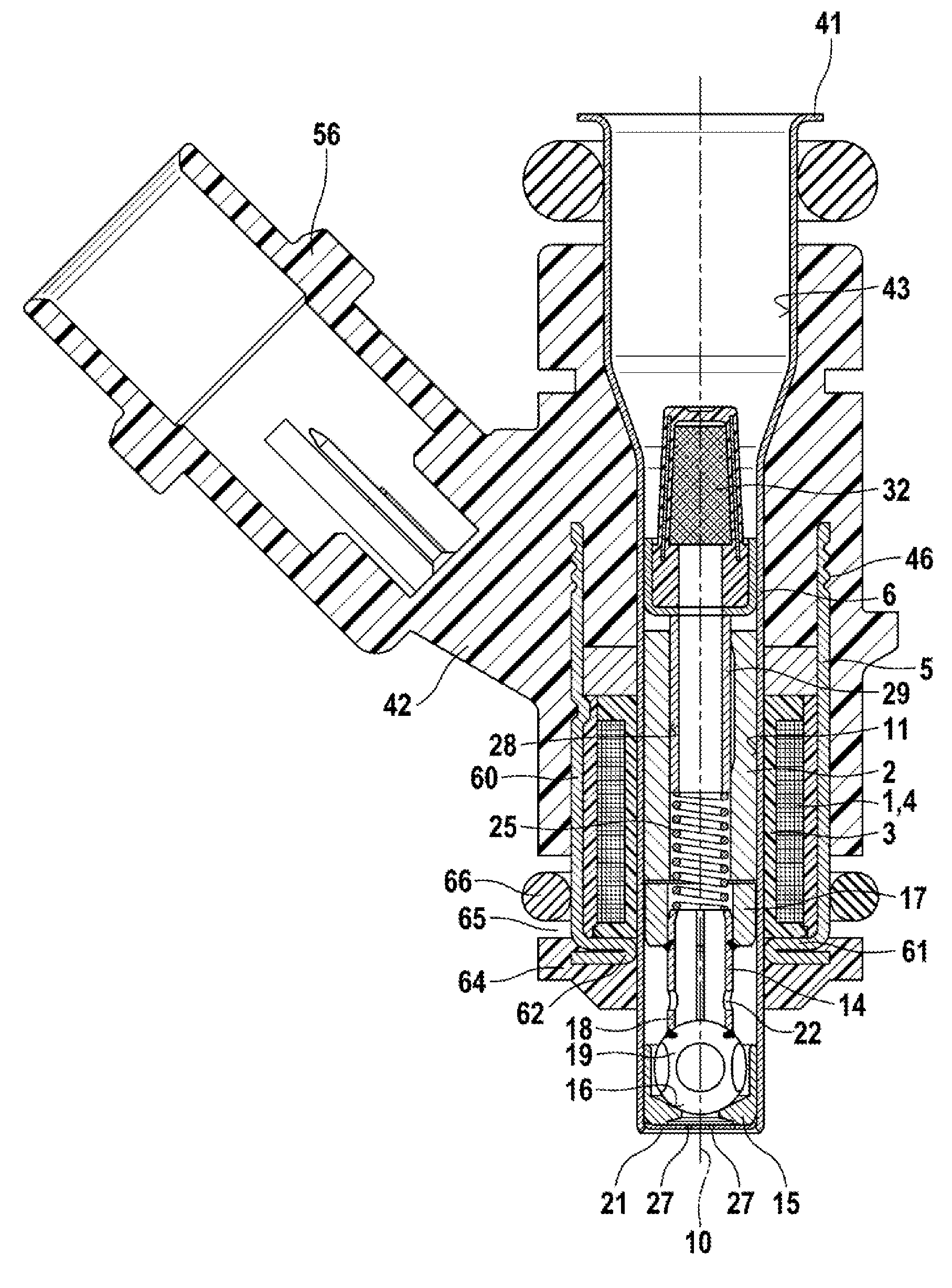
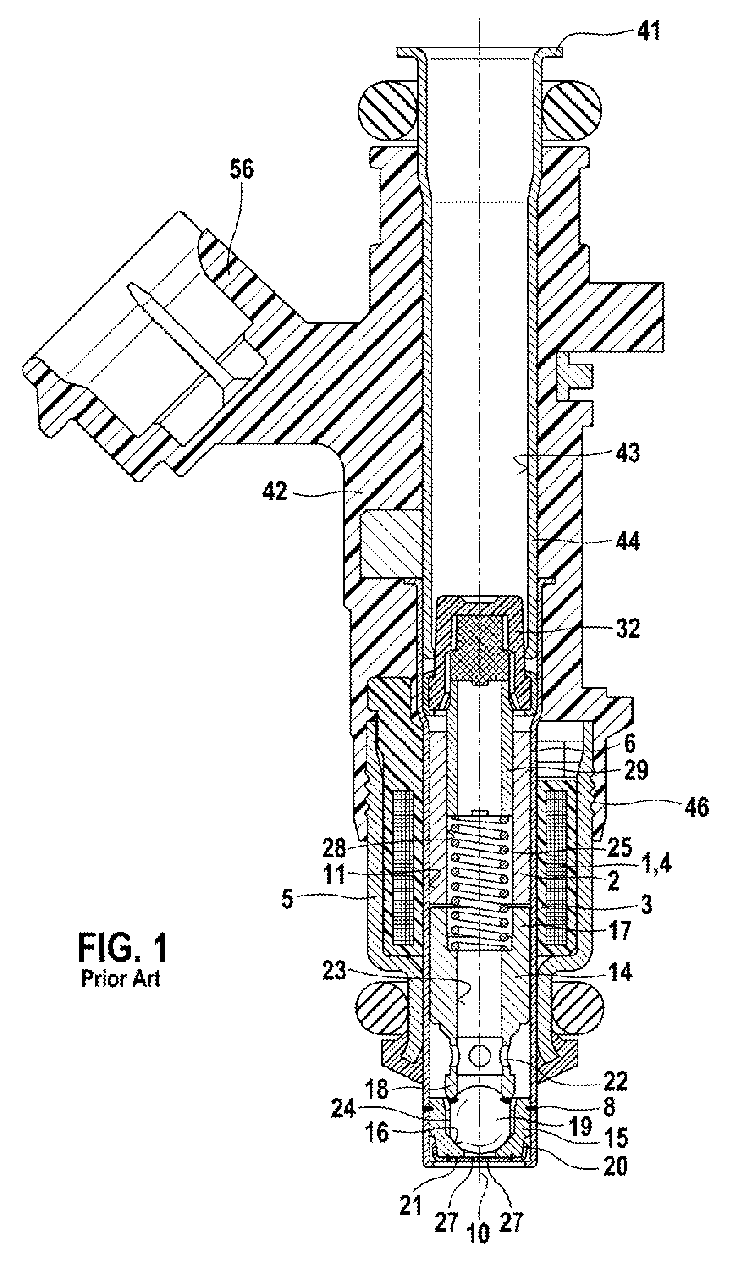
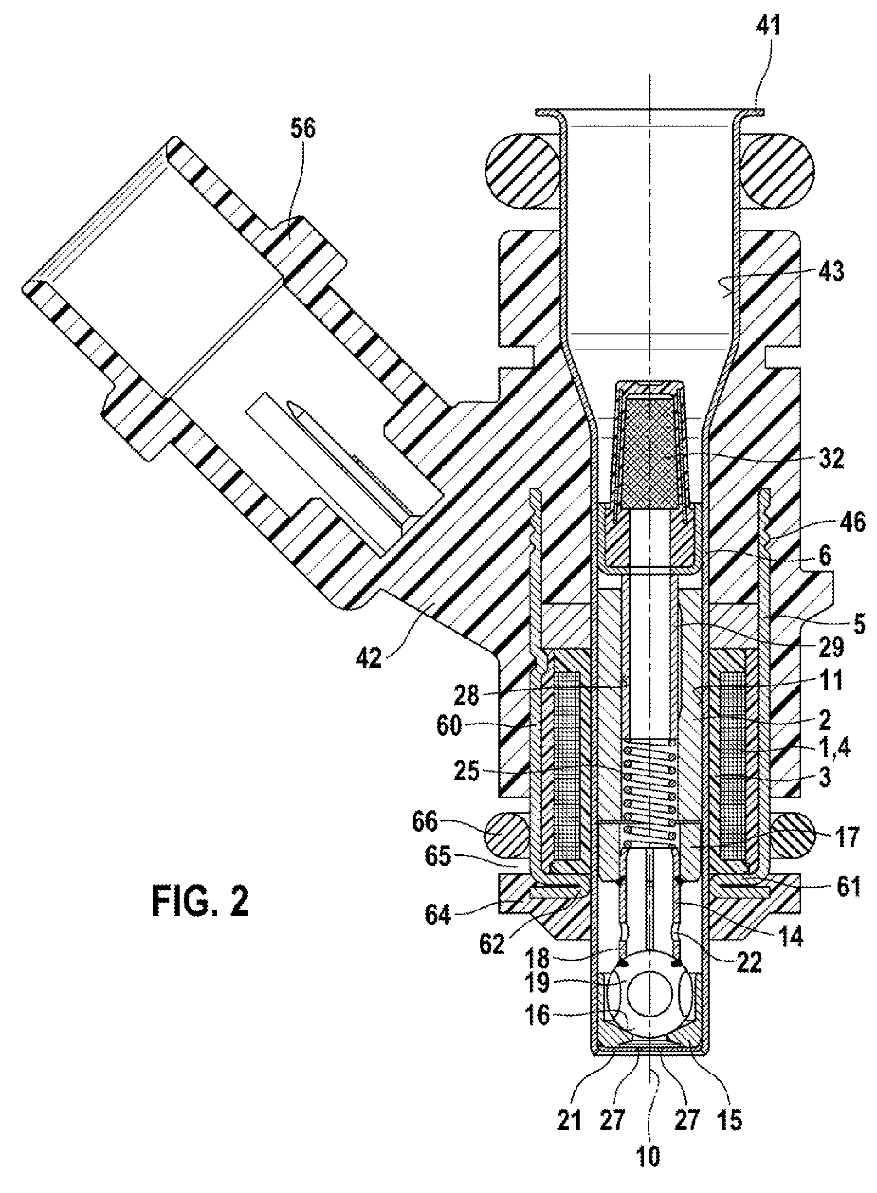
[0013]In order to understand the present invention, FIG. 1 shows, by way of example, an electromagnetically operable valve in the form of a fuel injector for fuel-injection systems of mixture-compressing internal combustion engines with externally supplied ignition according to the related art.

[0014]The valve has a substantially tubular core 2 which is surrounded by a solenoid coil 1 and is used as internal pole and partially as fuel passage. Solenoid coil 1 is surrounded completely in the circumferential direction by an outer, sleeve-shaped and graduated, e.g., ferromagnetic valve casing 5, which represents an outer magnetic-circuit component used as external pole. Solenoid coil 1, core 2 and valve casing 5 together form an electrically excitable actuating element.

[0015]While solenoid coil 1, embedded in a coil form 3 and having a winding 4, surrounds a valve sleeve 6 from outside, core 2 is mounted in an inner opening 11 in valve sleeve 6, the opening running concentrically relati...


PUM


Abstract

A fuel injector for fuel-injection systems of internal combustion engines. The valve includes an electromagnetic actuating element having a solenoid coil, a fixed core, an outer magnetic-circuit component and a movable armature to actuate a valve-closure member which cooperates with a valve-seat surface provided on a valve-seat member. The valve is characterized by its extremely small outside dimensions. The entire axially movable valve needle, including armature and valve-closure member, has a mass of only m<=0.8 g. The valve is suitable as a fuel injector, especially for use in fuel-injection systems of mixture-compressing internal combustion engines with externally supplied ignition.

Description

FIELD OF THE INVENTION[0001]The present invention is based on a fuel injector for a fuel-injection system of an internal combustion engine.BACKGROUND INFORMATION[0002]The German Patent DE 38 25 134 A1 discusses a fuel injector that includes an electromagnetic actuating element having a solenoid coil, having an internal pole and having an outer magnetic-circuit component and a movable valve-closure member that cooperates with a valve seat assigned to a valve-seat member. The injector is surrounded by a plastic coating, the plastic coating first and foremost extending in the axial direction, surrounding the fitting used as internal pole and the solenoid coil. At least in the area surrounding the solenoid coil, ferromagnetic fillers conducting magnetic lines of force are introduced in the plastic coating. In this respect, the fillers surround the solenoid coil in the circumferential direction. The fillers are pieces of metal reduced to fine grain and having soft-magnetic properties. Th...

Claims


Application Information

Patent Timeline
Patent Type & Authority Applications(United States)
IPC IPC(8): F02M51/06
CPCF02M51/0682F02M2200/08F02M51/06H01F7/1607F02M2200/9061
Inventor TERASHIMA, HIROKAZUGESK, MARKUSMOSER, FRIEDRICHSOHM, VOLKER
Owner ROBERT BOSCH GMBH
Why Eureka
Try Eureka