
Piston engine drivable using a steam power process

a steam power process and piston engine technology, applied in the field of piston engines, can solve the problem of inflexible structure form, and achieve the effect of sufficient working volume and good degree of efficiency

Inactive Publication Date: 2013-05-16
ROBERT BOSCH GMBH
View PDF7 Cites 1 Cited by
  • Summary
  • Abstract
  • Description
  • Claims
  • Application Information

AI Technical Summary

Benefits of technology

The piston engine described in this patent has the advantage of being highly efficient in a compact design. It can be used in places where space is limited and still provide enough power. Additionally, when combined with an internal-combustion engine, it can help to convert waste heat into additional driving energy. This results in reduced fuel consumption and increased efficiency in vehicles that use waste heat.

Problems solved by technology

Owing to the cylinders located at both sides of the crankshaft, however, this structural form does not have a flexible orientation of the cylinders because the possible fitting positions are limited.

Method used


Image

  • Piston engine drivable using a steam power process
  • Piston engine drivable using a steam power process
  • Piston engine drivable using a steam power process

Examples


first embodiment

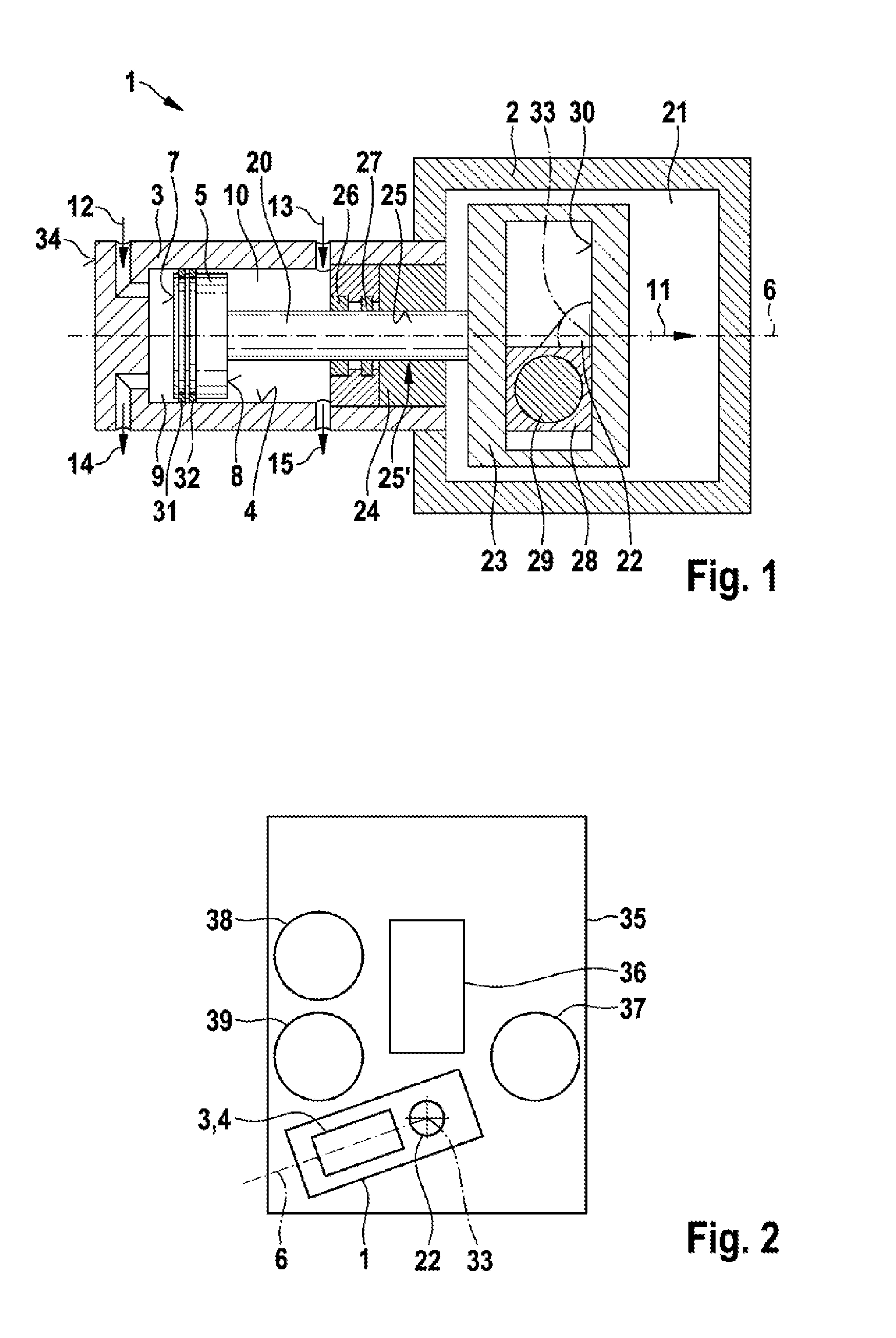
[0031]FIG. 1 is a schematic illustration of a piston engine 1 in accordance with the invention. The piston engine 1 is driven via a steam power process. In this instance, the piston engine 1 can be used particularly in an internal-combustion engine of a motor vehicle in order to use the waste heat of the internal-combustion engine. The piston engine 1 then converts the waste heat into mechanical energy which can be used, for example, as additional drive energy or to drive an auxiliary unit, in particular an electrical generator. However, the piston engine 1 according to the invention is also suitable for other applications.

[0032]The piston engine 1 has a housing portion 2 and a cylinder 3 which is connected to the housing portion 2. In this embodiment, the piston engine 1 has precisely one cylinder 3.

[0033]The cylinder 3 of the piston engine 1 has a cylinder bore 4, in which a cylinder piston 5 is arranged. The cylinder piston 5 is arranged in this instance in the cylinder bore 4 in...

second embodiment

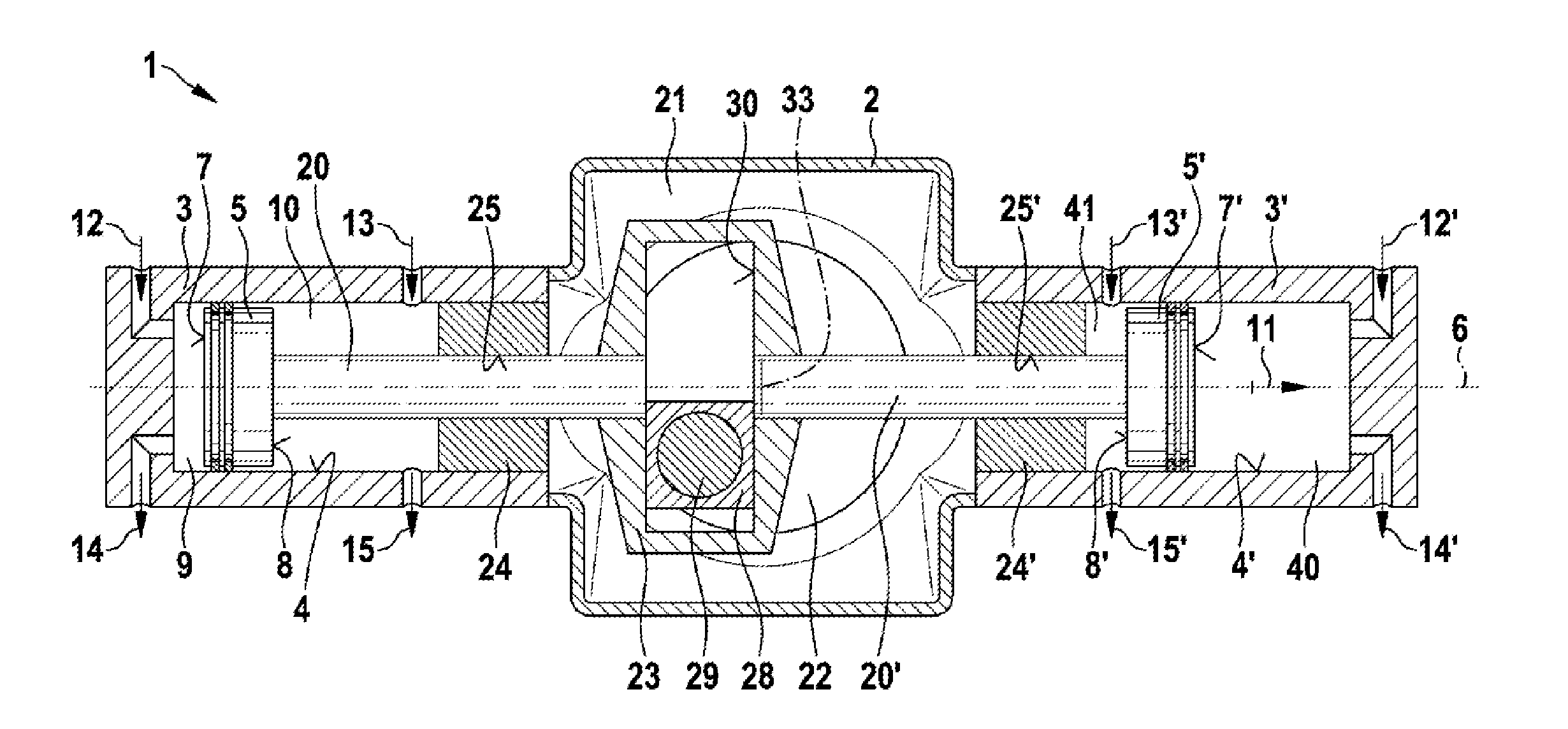
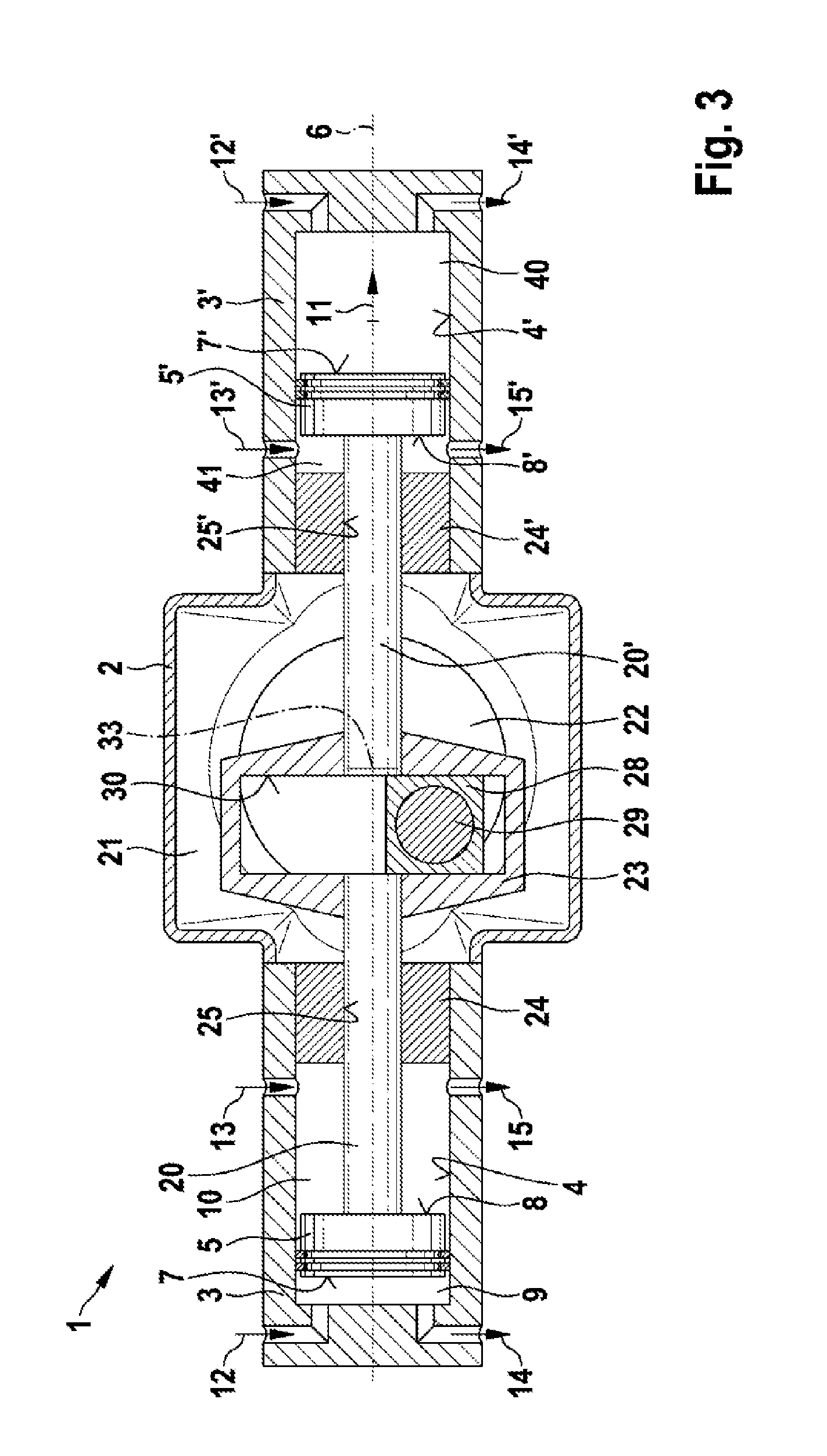
[0045]FIG. 3 is a schematic cross section of the piston engine 1 illustrated in FIG. 1 in accordance with a In this embodiment, the piston engine 1 has an additional cylinder 3′. An additional cylinder bore 4′, in which an additional cylinder piston 5′ is arranged, is constructed in the additional cylinder 3′. The additional cylinder piston 5′ can also be actuated along the axis 6 in this instance. The cylinder piston 5′ has a first lateral face 7′ and a second lateral face 8′. At the first lateral face 7′, the cylinder piston 5′ delimits a third operating space 40. At the second lateral face 8′, the cylinder piston 5′ delimits a fourth operating space 41. The cylinder piston 5′ can be actuated together with the cylinder piston 5 so that both cylinder pistons 5 are displaced either in the direction 11 or counter to the direction 11.

[0046]Inlets 12′, 13′ are provided in the additional cylinder 3′. Furthermore, outlets 14′, 15′ are provided in the additional cylinder 3′. The inlet 12...


PUM


Abstract

A piston engine (1) that can be driven using a steam power process and is used in particular for utilizing waste heat from an internal combustion engine comprises at least one cylinder bore (4), a cylinder piston (5) which is arranged in the cylinder bore (4), and a rod (20) which is connected to the cylinder piston (5). The rod (20) is guided out of the cylinder bore (4). The cylinder piston (5) delimits a first operating space (9) and a second operating space (10) in the cylinder bore (4). A crankshaft (22) is disposed in a crankshaft space (21). The rod (20) is connected to a slider crank mechanism (23) which is disposed in the crankshaft space (21), the rod (20) being effectively connected to the crankshaft (22) via the slider crank mechanism (23), thus making it possible to obtain a large expansion volume while keeping the design of the piston engine (1) compact.

Description

BACKGROUND OF THE INVENTION[0001]The invention relates to a piston engine which can be driven via a steam power process. In particular, the invention relates to a piston engine which can be driven via a steam power process and which serves to use the waste heat of an internal-combustion engine.[0002]Internal-combustion engines convert the energy of the fuel into mechanical energy in order to drive vehicles and the like. However, a substantial portion of the energy is thereby released as waste heat which is directed away by the cooling system or in the exhaust gas of the internal-combustion engine. In order to use this thermal energy, it is conceivable for a steam power process to be coupled to the internal-combustion engine. The thermal energy from the internal-combustion engine can thereby be used to produce steam which is expanded in an expansion engine and which consequently provides additional energy which can be used to drive the vehicle or to produce auxiliary energy. In this ...

Claims


Application Information

Patent Timeline
Patent Type & Authority Applications(United States)
IPC IPC(8): F01B29/00
CPCF01B9/023F01B29/00Y02T10/166F02G5/02Y02T10/12
Inventor EISENMENGER, NADJAMAGEL, HANS-CHRISTOPHWENGERT, ANDREAS
Owner ROBERT BOSCH GMBH
Learn More