Cooling device for use in space environment

a cooling device and space environment technology, applied in lighting and heating apparatus, air humidification systems, heating types, etc., can solve the problems of deterioration in cooling efficiency and easy clogging of porous plates

Active Publication Date: 2013-10-03
MITSUBISHI HEAVY IND LTD
View PDF7 Cites 9 Cited by
  • Summary
  • Abstract
  • Description
  • Claims
  • Application Information

AI Technical Summary

Benefits of technology

The present invention is a cooling device designed for use in space that does not require high-purity water for cooling. The device includes a first flow path through which coolant is introduced, a second flow path that performs the cooling, and a water absorbing body exposed to the space environment. The water absorbing body contains a water-absorbing member made of polymer material that absorbs the coolant from the second flow path and transfers it to the space environment. The device also includes an outer pipe and an inner pipe, with the first flow path located inside the inner pipe and the second flow path located between the inner and outer pipes. Overall, the invention provides a cooling solution for use in space that is efficient and flexible.

Problems solved by technology

Cooling is one issue of devices used in the space environment.
For example, although a cooling device installed in a space suit is required to cool coolant, ambient air or environmental water (seawater and the like) is not available as a cooling source, differently from cooling devices used on the ground.
One issue of these cooling devices for use in the space environment is that the porous plate is easily clogged, if the purity of the water used for cooling is low.
This undesirably causes deterioration in the cooling efficiency.

Method used


Image

  • Cooling device for use in space environment
  • Cooling device for use in space environment
  • Cooling device for use in space environment

Examples


first embodiment

[0017]FIG. 2 is a cross-sectional view showing the structure of a cooling device 10, which is dedicated for use in the space environment, in a first embodiment of the present invention, and FIG. 3 is a perspective view showing the structure of the cooling device 10. The cooling device 10 includes an inner pipe 11, an outer pipe 12 and a water absorbing body 15. The water absorbing body 15 is disposed to surround the outer face of the outer pipe 12.

[0018]The inner pipe 11 is housed in the outer pipe 12. The space inside the inner pipe 11 is used as an inner flow path 13 and the spaces between the inner pipe 11 and the outer pipe 12 are used as outer flow paths 14. As described later, coolant to be cooled flows through the inner flow path 13 and feedwater to be evaporated or sublimated flows through the outer flow paths 14. In this embodiment, the inner pipe 11 and the outer pipe 12 are both made of metal having a superior thermal conductivity, such as copper. This means that the inne...

second embodiment

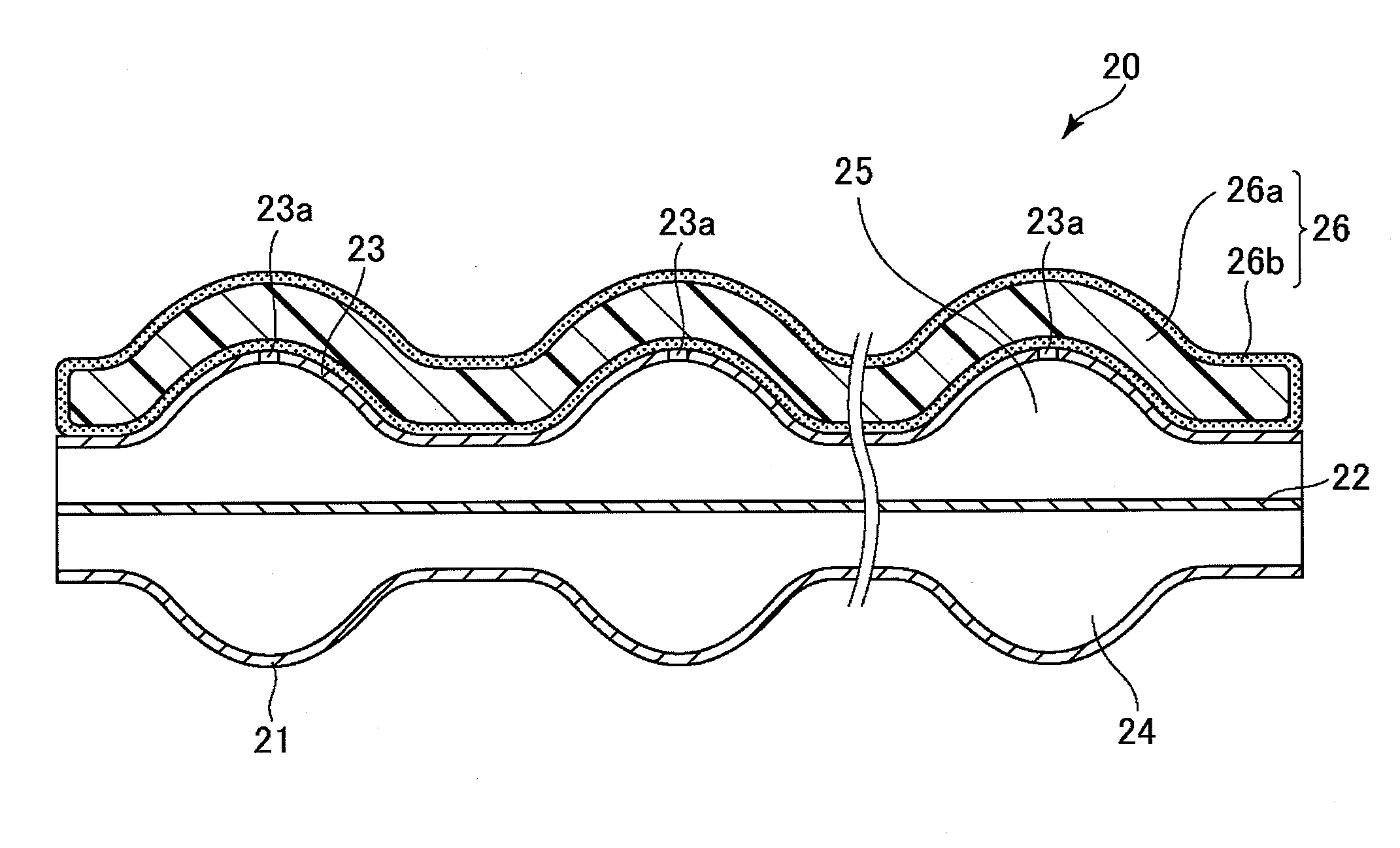
[0027]FIG. 4 is a cross-sectional view showing the structure of a cooling device 20 dedicated for use in the space environment in the second embodiment of the present invention. The cooling device 20 includes a rear plate 21, a partition wall 22, a front plate 23 and a water absorbing body 26. The rear plate 21 and the partition wall 22 are placed opposed to each other, and a coolant flow path 24 is formed between the rear plate 21 and the partition wall 22. Furthermore, a feedwater flow path 25 is formed between the partition wall 22 and the front plate 23. The rear plate 21, the partition wall 22 and the front plate 23 are all made of metal having a superior thermal conductivity, such as copper. This means that the coolant flow path 24 and the feedwater flow path 25 are thermally coupled, allowing heat exchange between the coolant flowing through the coolant flow path 24 and the feedwater flowing through the feedwater flow path 25.

[0028]The front plate 23 has protrusions which pro...


PUM


Abstract

A space-environment dedicated cooling device includes a first flow path to which coolant to be cooled is fed, a second flow path thermally coupled to the first flow path and a water absorbing body which is exposed to the space environment when the cooling device is used in the space environment. The second flow path is fed with feedwater. The water absorbing body is fed with the feedwater from the second flow path. The water absorbing body includes a water absorbing member made of water-absorbing material.

Description

TECHNICAL FIELD[0001]The present invention relates to a cooling device dedicated for use in the space environment, more particularly, relates to a cooling device that uses latent heat of evaporation of water for cooling an object to be cooled in the space environment.BACKGROUND ART[0002]Cooling is one issue of devices used in the space environment. For example, although a cooling device installed in a space suit is required to cool coolant, ambient air or environmental water (seawater and the like) is not available as a cooling source, differently from cooling devices used on the ground. This implies that a cooling technique different from that used on the ground is required for achieving cooling in the space environment.[0003]One known cooling device for use in the space environment is a sublimator, which uses the latent heat of evaporation of water to cool an object. A sublimator is disclosed in Rubik B. Sheth et al., “Investigation of Transient Performance for a Sublimator”, 41st...

Claims


Application Information

Patent Timeline
IPC IPC(8): B64G1/50F24F5/00
CPCB64G1/50F24F6/043F25B19/00F25B39/02B64G6/00F28F3/042F28F13/003F28D7/10F28D7/106F28D21/0015F28F1/06F28F1/08F28D2021/0064F28D2021/0021F28D2021/0071F24F5/0035Y02B30/54
Inventor SATO, TATSUYAKANAZAWA, RYOICHI
Owner MITSUBISHI HEAVY IND LTD
Why Eureka
Try Eureka