
Substrate cleaning apparatus and substrate processing apparatus including the substrate cleaning apparatus

a cleaning apparatus and substrate technology, applied in cleaning equipment, separation of dispersed particles, separation processes, etc., can solve the problems of insufficient adherence of mist (microdroplets) or particles to substrates, inability to supply clean air to a space, and inability to prevent mist (microdroplets) from forming etc., to prevent contamination of photosensitive films formed on the upper surface of substrates.

Active Publication Date: 2013-10-03
SCREEN SEMICON SOLUTIONS CO LTD
View PDF6 Cites 9 Cited by
  • Summary
  • Abstract
  • Description
  • Claims
  • Application Information

AI Technical Summary

Benefits of technology

The patent describes a substrate cleaning apparatus that can prevent contamination on both the upper and lower surfaces of a substrate during semiconductor device manufacturing. The apparatus creates a flow of clean air that prevents processing liquid or particles from entering the space between the substrate and the rotating member. This allows for cleaning of the substrate's lower surface while keeping the upper surface clean, which can help prevent processing defects and contamination on the photosensitive film formed on the substrate. Overall, the apparatus aims to improve semiconductor device manufacturing efficiency and reliability.

Problems solved by technology

Adherence of a mist (microdroplets) or particles to a substrate, however, may not be prevented sufficiently even when the downflow is formed in each processing chamber.
In this case, even though a downflow is formed in the cleaning / drying processing unit, clean air is not supplied to a space between the spin plate and the substrate.

Method used


Image

  • Substrate cleaning apparatus and substrate processing apparatus including the substrate cleaning apparatus
  • Substrate cleaning apparatus and substrate processing apparatus including the substrate cleaning apparatus
  • Substrate cleaning apparatus and substrate processing apparatus including the substrate cleaning apparatus

Examples


Embodiment Construction

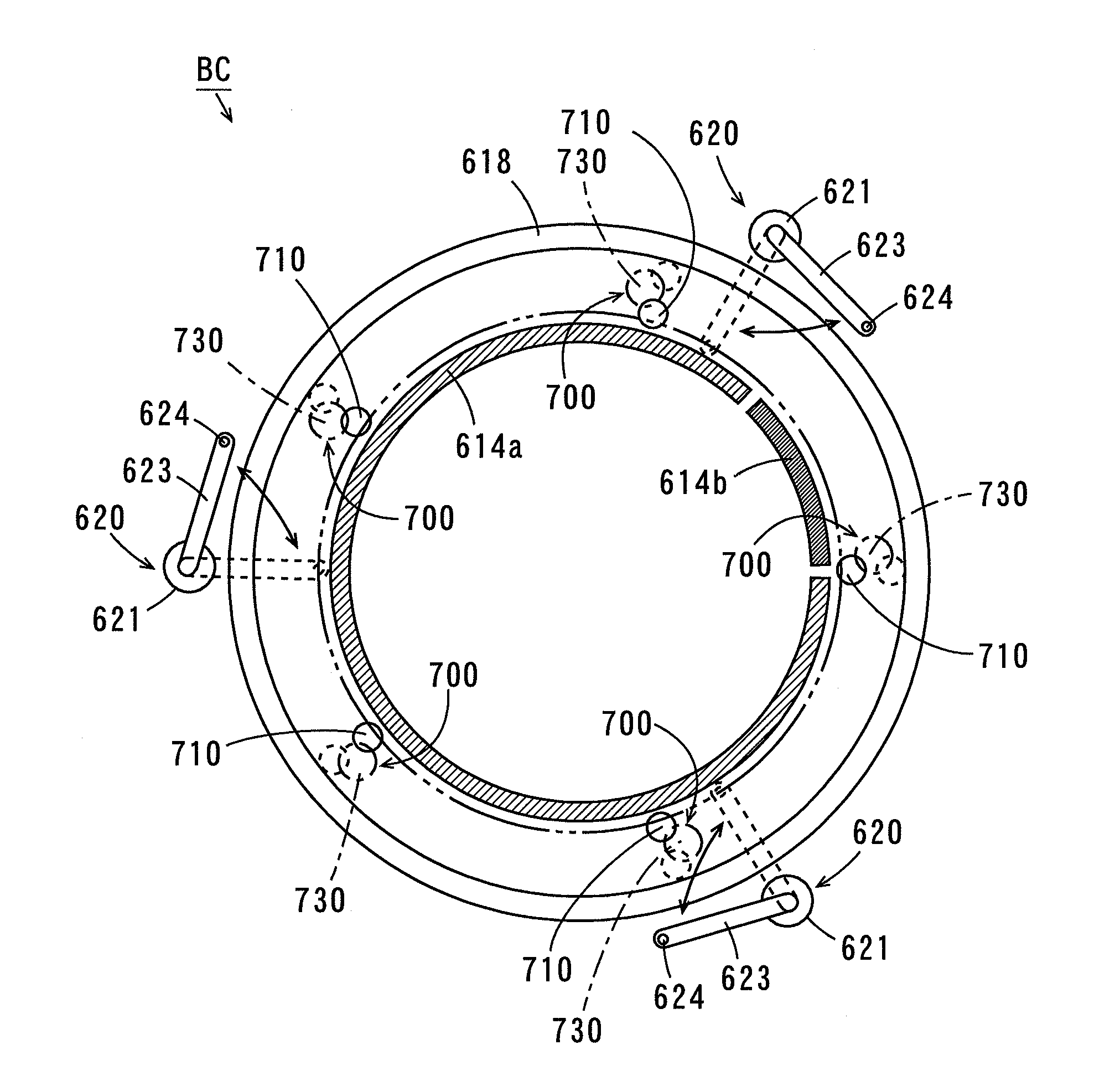
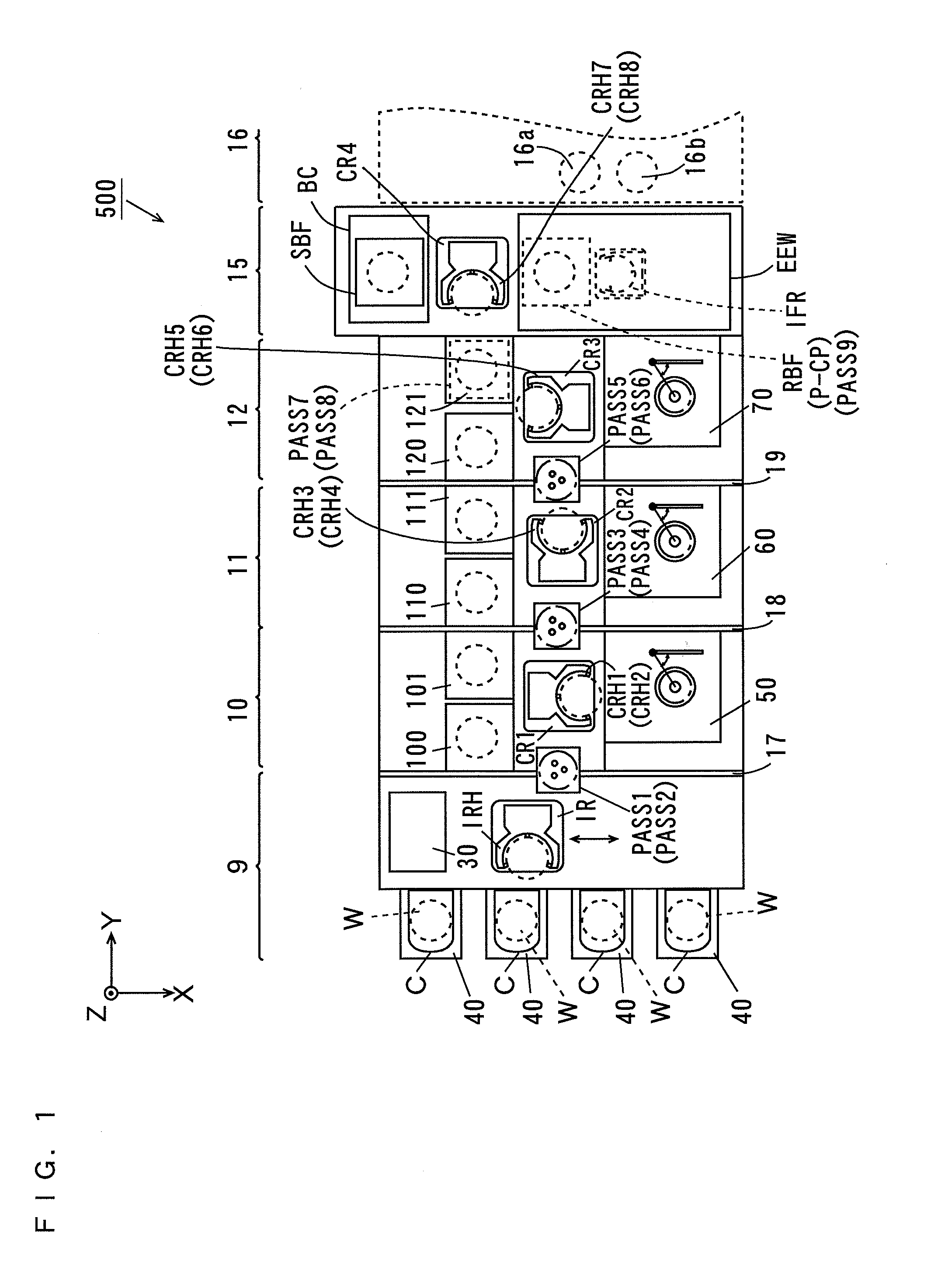
[0046]A substrate cleaning apparatus and a substrate processing apparatus including the substrate cleaning apparatus according to an embodiment of the present invention will be described below with reference to the drawings. In the following description, a substrate refers to a semiconductor substrate, a substrate for a liquid crystal display, a substrate for a plasma display, a glass substrate for a photomask, a substrate for an optical disc, a substrate for a magnetic disc, a substrate for a magneto-optical disc, a substrate for a photomask or the like. In the present embodiment, a back surface cleaning processing unit that performs cleaning processing on a back surface of the substrate before exposure processing will be described as one example of the substrate cleaning apparatus.

(1) Configuration of Substrate Processing Apparatus

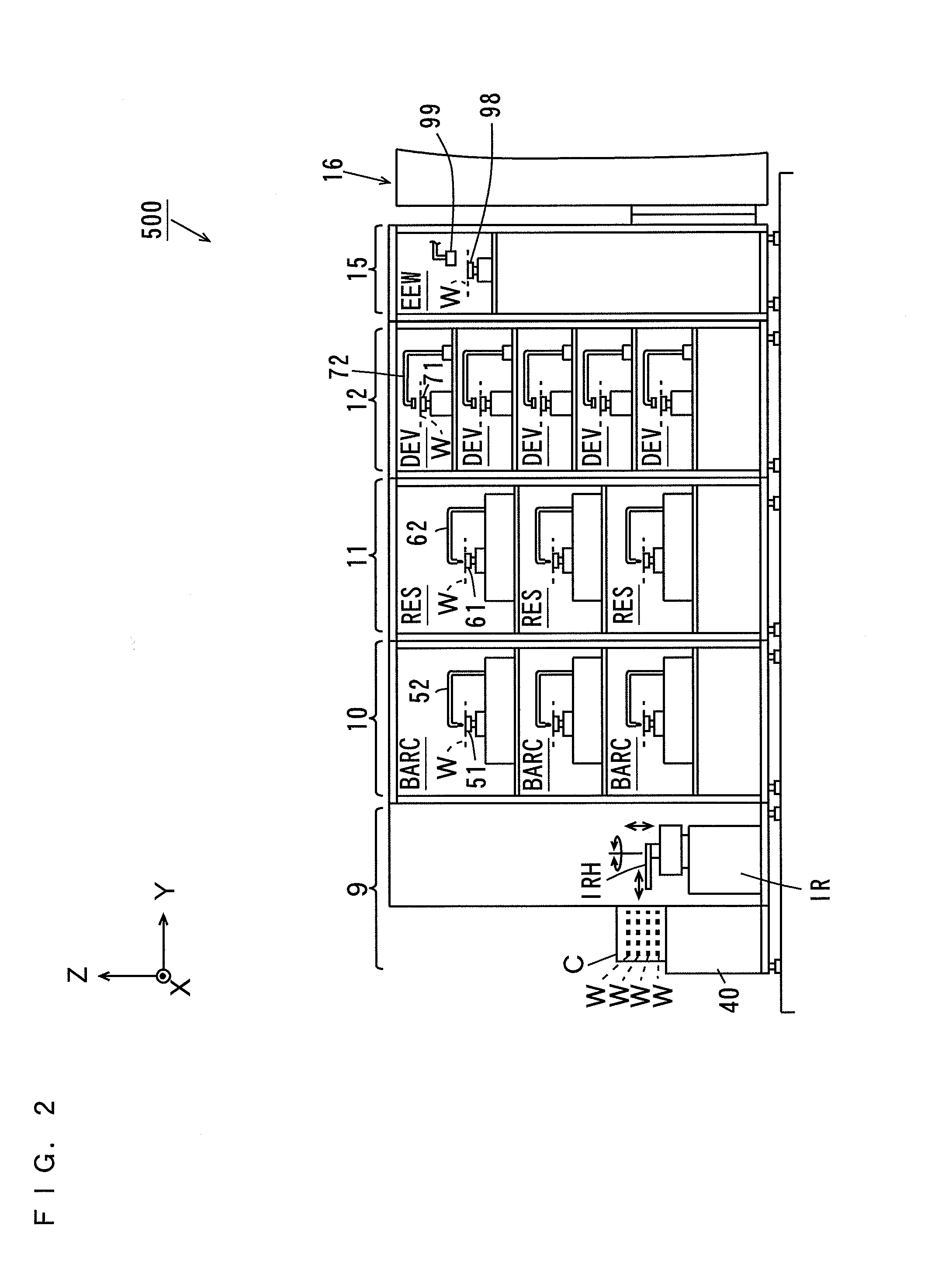
[0047]FIG. 1 is a plan view of the substrate processing apparatus according to one embodiment of the present invention. A substrate processing apparatus...


PUM

PropertyMeasurementUnit
Areaaaaaaaaaaa
Photosensitivityaaaaaaaaaa

Abstract

An ULPA filter is arranged at the upper portion in a casing. Air outside of the casing is supplied to the ULPA filter through a duct. Clean air that has passed through the ULPA filter is led to an opening of a spin plate through a passage forming member, a connection member, a base, a motor supporting member and a rotating shaft of a spin motor. The spin chuck holds a substrate such that the upper surface of the substrate is opposite to the spin plate. In this state, the spin motor operates, causing the spin plate to rotate and thus the lower surface of the rotating substrate to be cleaned by a cleaning brush.

Description

BACKGROUND OF THE INVENTION[0001](1) Field of the Invention[0002]The present invention relates to a substrate cleaning apparatus and a substrate processing apparatus including the substrate cleaning apparatus.[0003](2) Description of Related Art[0004]Substrate processing apparatuses have been conventionally used to subject substrates such as semiconductor wafers, glass substrates for photomasks, liquid crystal displays, and glass substrates for optical discs to various types of processing.[0005]The substrate processing apparatus as described in JP 2006-019584 A includes a plurality of processing chambers. A fan filter unit is arranged above each processing chamber and an exhaust duct is connected to the lower portion of each processing chamber. The air in a clean room is supplied to each processing chamber through a filter in the fan filter unit and is exhausted through the exhaust duct from the processing chamber. In this case, a downflow of clean air is formed in each processing c...

Claims


Application Information

Patent Timeline
IPC IPC(8): B08B1/04
CPCH01L21/67046B08B1/04H01L21/68742H01L21/68728H01L21/67051H01L21/02057H01L21/02096H01L2021/60187B01D46/0002H01L21/6704
Inventor NISHIYAMA, KOJI
Owner SCREEN SEMICON SOLUTIONS CO LTD
Learn More