Impact attenuator for vehicles

a technology of attenuators and vehicles, applied in the direction of elastic dampers, springs/dampers, ways, etc., can solve the problems of affecting the function, affecting the braking effect, so as to increase the braking action, the effect of increasing the bending strength and increasing the width

Active Publication Date: 2013-09-26
BIRSTAVERKEN
View PDF4 Cites 2 Cited by
  • Summary
  • Abstract
  • Description
  • Claims
  • Application Information

AI Technical Summary

Benefits of technology

The patent describes an energy absorbing device or brake that can decelerate and absorb the force of a collision. The device has a unique design that allows for a large braking action at the end of the braking distance, which is important for safely stopping vehicles of different sizes. The device is compact and can be made at a low cost. The braking action is achieved by positioning the pins and draw element in a way that allows for a large change of direction of at least 90° at each passage of at least two pins. This large braking action can be utilized to restrict the number of pins and make the housing compact with small dimensions. The device can be made more compact and shorter in relation to one where all of the pins are positioned in the same plane. The brake also has a progressively increasing braking action, which is larger in the end of the braking distance than in the beginning, to ensure a safe stop for vehicles of different sizes.

Problems solved by technology

One problem with such impact attenuators is that they have to be durable, i.e. have to be in working order during years, maybe several decades of inactivity until someday an accident occurs and then they have to function without having been negatively affected during the lapse of time due to e.g. corrosion, intense contamination of dirt or the like which can make movable parts to jam and be completely blocked such that the function is jeopardized.

Method used


Image

  • Impact attenuator for vehicles
  • Impact attenuator for vehicles
  • Impact attenuator for vehicles

Examples


Embodiment Construction

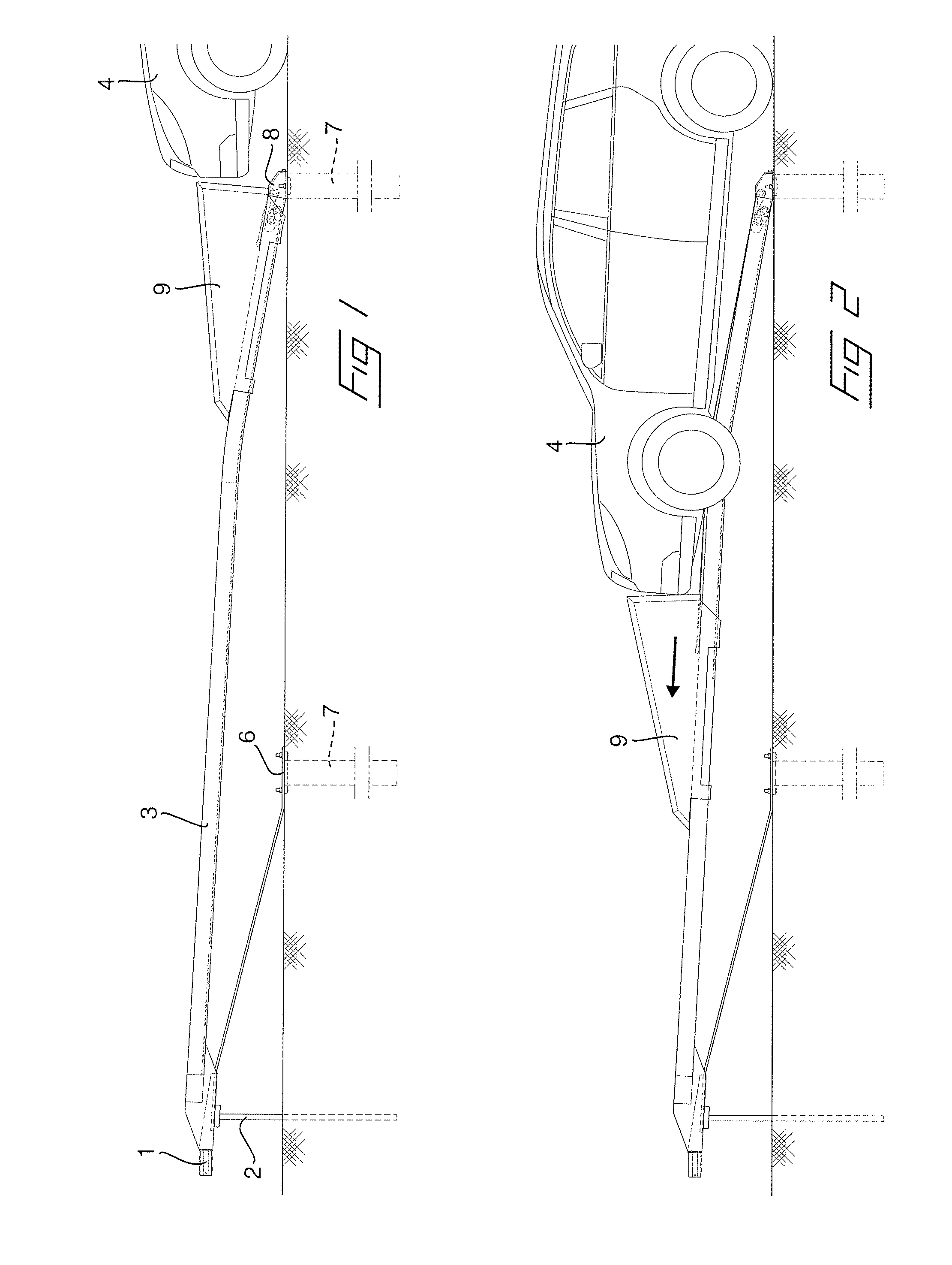
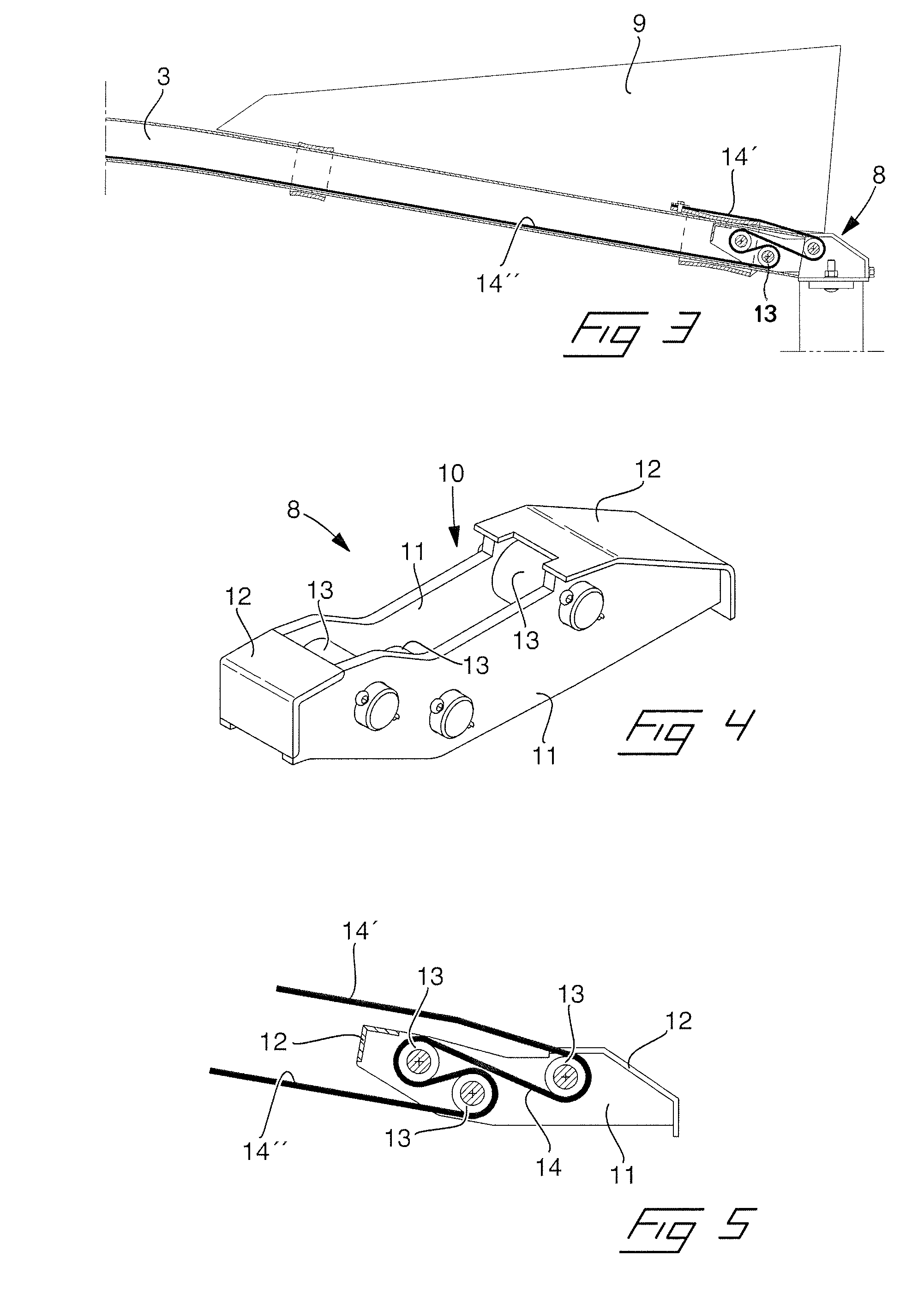
[0025]Firstly, an energy absorbing device will be described according to a first embodiment and the application of the same at an impact attenuator for collisions with vehicles at an end of a safety barrier. In FIG. 1, the end of the safety barrier is shown with the impact attenuator in an initial position. The safety barrier according to the illustrated embodiment is of the type which is composed of a safety barrier beam 1 having a rectangular cross section which is supported on a distance above a roadway by means of safety barrier posts 2, which are driven down through the roadway and into the roadbed. Of the actual safety barrier only the outermost end and the last safety barrier post 2 are shown. From the safety barrier extends a safety barrier terminal in form of a safety barrier terminal beam 3, having likewise a rectangular, hollow cross section, which in its one end is fixedly connected to the safety barrier and is sloping downwards to abutment against the roadway in its oth...


PUM


Abstract

An impact attenuator for vehicles, including an energy absorbing device for decelerating forces, including a housing, at least two pins arranged in the housing which are arranged in parallel to each other in the housing, as well as a metallic, elongated draw element, which can be positioned within the housing such that it extends between and in contact with the pins, wherein the pins and the draw element are positioned such that a change of direction appears on the draw element when passing by each pin such that at mutual moving of the draw element and the housing in relation to each other, the movement is decelerated due to deformation of the draw element at passage of each pin. The pins and the draw element are positioned such that the draw element obtains a change of direction of at least 90° when passing at least two of the pins.

Description

[0001]The present invention relates to an impact attenuator for vehicles, including an energy absorbing device for decelerating forces, comprising a housing, at least two pins arranged in the housing which are arranged in parallel to each other in the housing, as well as a metallic, elongated draw element, which can be positioned within the housing such that it extends between and in contact with the pins, wherein the pins and the draw element are positioned such that a change of direction appears on the draw element when passing by each pin such that at mutual moving of the draw element and the housing in relation to each other, the movement is decelerated due to deformation of the draw element at passage of each pin, wherein the pins and the draw element are positioned such that the draw element obtains a change of direction of at least 90° when passing at least two of the pins, respectively.BACKGROUND OF THE INVENTION[0002]In many connections there is a need for impact attenuator...

Claims


Application Information

Patent Timeline
IPC IPC(8): E01F15/14F16F7/12
CPCF16F7/123E01F15/146F16F7/12E01F15/14
Inventor GISSLIN, LARS- KE
Owner BIRSTAVERKEN
Why Eureka
Try Eureka