
Using Alternative Stimulus Waveforms To Improve Pitch Percepts Elicited With Cochlear Implant Systems

Inactive Publication Date: 2013-09-19
MED EL ELEKTROMEDIZINISCHE GERAETE GMBH
View PDF3 Cites 15 Cited by
  • Summary
  • Abstract
  • Description
  • Claims
  • Application Information

AI Technical Summary

Benefits of technology

The patent text describes a cochlear implant system that uses different waveforms for electrode stimulus signals. These signals can more effectively excite the distal ends or mid-portions of peripheral neural processes in the cochlea, as opposed to exciting the spiral ganglion cells in the cochlea. The use of balanced biphasic pulses with relatively high amplitudes and short durations for each phase may be effective in exciting the peripheral processes. This selective excitation of the peripheral processes can lead to more spatial specificity of excitation and a stochastic pattern of neural responses. It can also eliminate or reduce confusions and reversals among the pitches elicited by different electrodes at the apical end of the implanted array. The stimulus waveforms mentioned in the patent text include balanced biphasic rectangular pulses, triphasic, pseudo-monophasic, exponential ramp shape, and exponentially decaying shape. The potential benefits of selective stimulation at the apex include better perception of speech, music, and environmental sounds, as well as greater spatial specificity of excitation and a more stochastic pattern of neural responses. The manipulations in phase duration (PD) may be needed for only a subset of the apical electrodes or all of them. In rare cases, no manipulations in PD would be needed.

Problems solved by technology

Hearing is impaired when there are problems in the ability to transmit sound from the external to the inner ears or problems in the transducer function within the inner ear.
CI users can have some difficulty perceiving the electrode stimulation signals according to their position in the cochlea.

Method used


Image

  • Using Alternative Stimulus Waveforms To Improve Pitch Percepts Elicited With Cochlear Implant Systems
  • Using Alternative Stimulus Waveforms To Improve Pitch Percepts Elicited With Cochlear Implant Systems
  • Using Alternative Stimulus Waveforms To Improve Pitch Percepts Elicited With Cochlear Implant Systems

Examples


Embodiment Construction

[0016]Electrical stimulation at apical locations in the ST can elicit pitch percepts that are not discriminable from one another or that are not ordered from high to low with progressively more apical locations. Such confusions and reversals in pitch can occur at other locations, i.e., basal or middle locations, but the confusions and reversals are far more frequent at the apical locations. A lack of discrimination for all pairings of electrodes, or a reversal or reversals in pitch, may degrade hearing abilities—such as speech or music perception—with CI systems.

[0017]The predominance of confusions and reversals for the apical locations in the ST is thought to arise from the anatomy of the cochlea. In particular, the SGCs follow the course of cochlear spiral (and the course of the ST) up to about the second turn of the cochlea but then end in a terminal bulb at that level. Peripheral processes projecting from the SCGs within the terminal bulb innervate the sensory structures in the ...


PUM


Abstract

A cochlear implant system is described which includes an electrode array for implantation in the scala tympani of a cochlea. Electrodes on the outer surface of the electrode array apply electrode stimulation signals to nearby neural tissue. An implantable stimulator module develops the electrode stimulation signals. The electrode stimulation signals have different waveforms. A basal waveform for one or more electrodes at the basal end of the electrode array has the form of a sequence of conventional high-amplitude short-duration electrode stimulation signals. An apical waveform for one or more electrodes at the apical end of the electrode array has the form of a sequence of lower-amplitude longer-duration electrode stimulation signals. The apical waveform is adapted to selectively stimulate peripheral neural processes towards the apical end of the electrode array so as to provide a tonotopic place-pitch response to the electrode stimulation signals.

Description

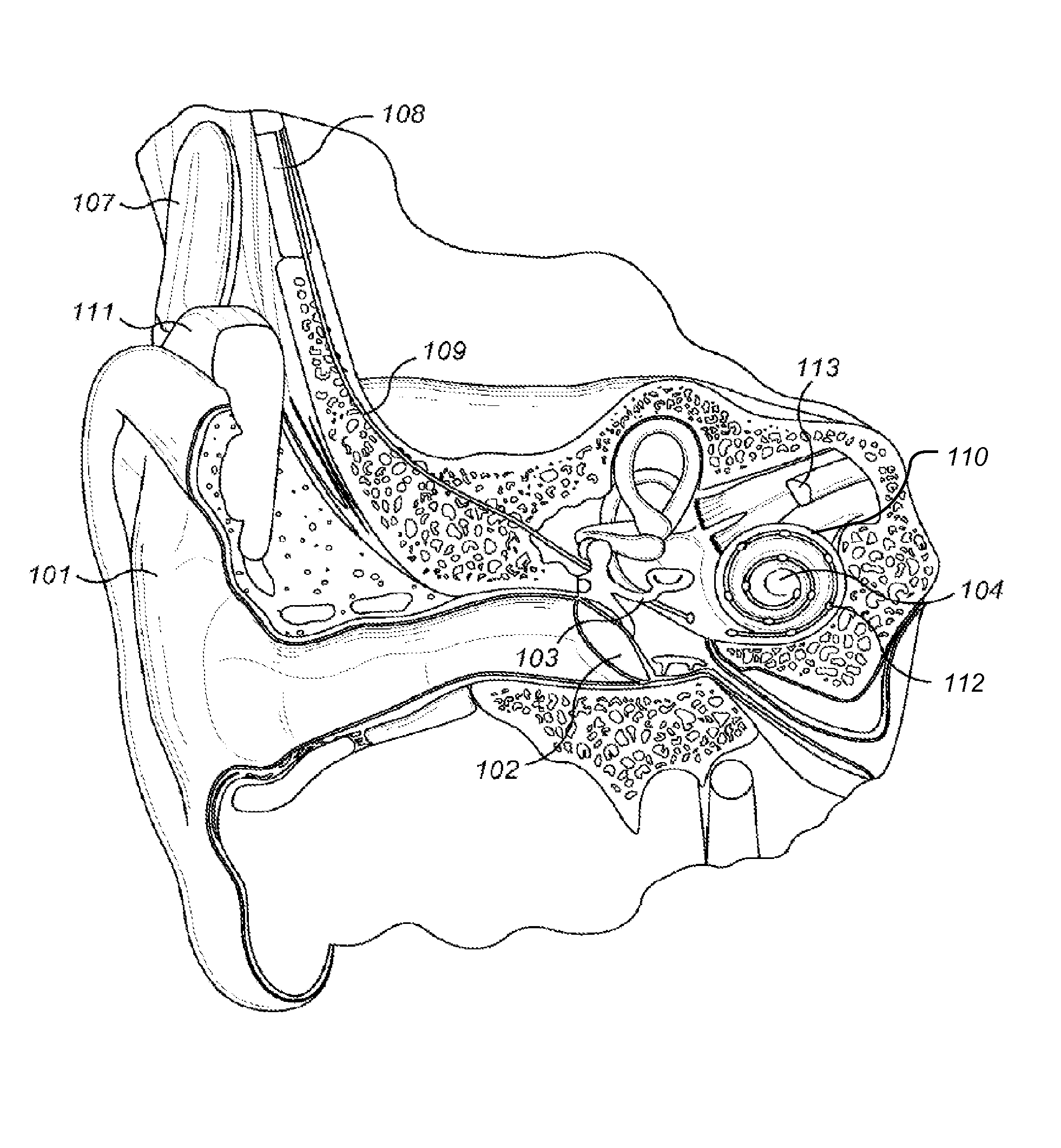
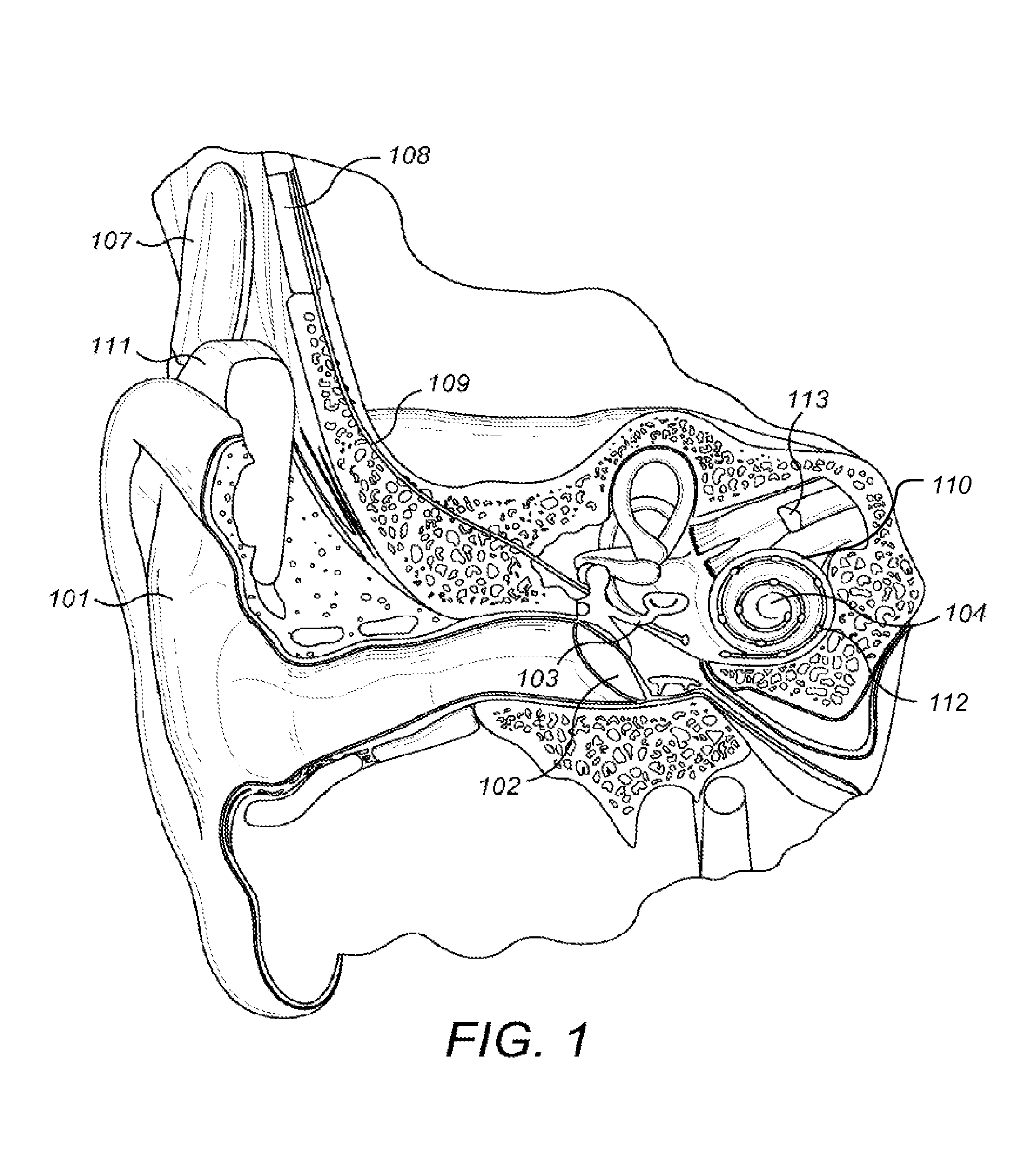
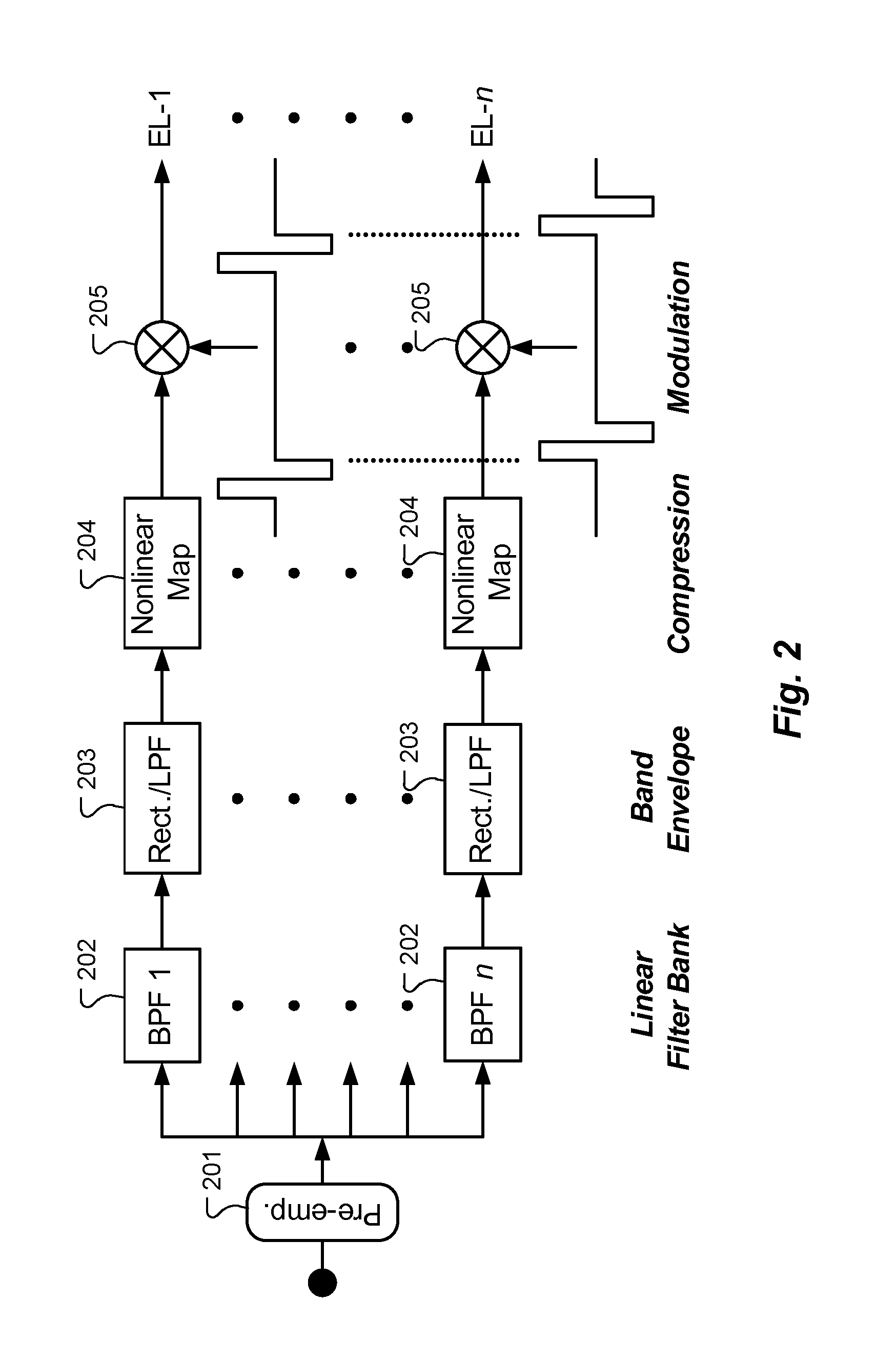
[0001]This application claims priority from U.S. Provisional Patent Application 61 / 611,122, filed Mar. 15, 2012, which is incorporated herein by reference.TECHNICAL FIELD[0002]The present invention relates to cochlear implant (CI) systems that use electrodes placed in the scala tympani (ST) of the cochlea.BACKGROUND ART[0003]A human ear normally transmits sounds such as speech sounds as shown in FIG. 1 through the outer ear 101 to the tympanic membrane (eardrum) 102, which moves the bones of the middle ear 103 (malleus, incus, and stapes) that vibrate the oval window membrane of the cochlea 104. The cochlea 104 is a long narrow duct wound spirally about its axis for approximately two and three quarters turns. It includes three chambers along its length: an upper chamber known as the scala vestibuli, a middle chamber known as the scala media, and a lower chamber known as the scala tympani (ST). The cochlea 104 forms an upright spiraling cone with a center called the modiolus where th...

Claims


Application Information

Patent Timeline
IPC IPC(8): A61N1/36
CPCA61N1/0541A61N1/36032A61N1/36038
Inventor STOHL, JOSHUAWILSON, BLAKE S.
Owner MED EL ELEKTROMEDIZINISCHE GERAETE GMBH
Learn More