System for detecting defects on an aircraft engine impeller wheel

a technology for aircraft engines and impeller wheels, applied in the direction of machines/engines, combustion air/fuel air treatment, instruments, etc., can solve problems such as complex implementation and affecting the correct operation of engines

Active Publication Date: 2013-09-19
SN DETUDE & DE CONSTR DE MOTEURS DAVIATION S N E C M A
View PDF9 Cites 7 Cited by
  • Summary
  • Abstract
  • Description
  • Claims
  • Application Information

AI Technical Summary

Problems solved by technology

An aircraft engine comprises several impeller wheels that are potentially exposed to undergoing impacts that can damage them and, consequently, affect the correct operation of the engine.
However, these methods do not apply to on-board rotating systems because they require a costly instrumentation which has to be partially supported by the rotors, leading to...

Method used


Image

  • System for detecting defects on an aircraft engine impeller wheel
  • System for detecting defects on an aircraft engine impeller wheel
  • System for detecting defects on an aircraft engine impeller wheel

Examples


Embodiment Construction

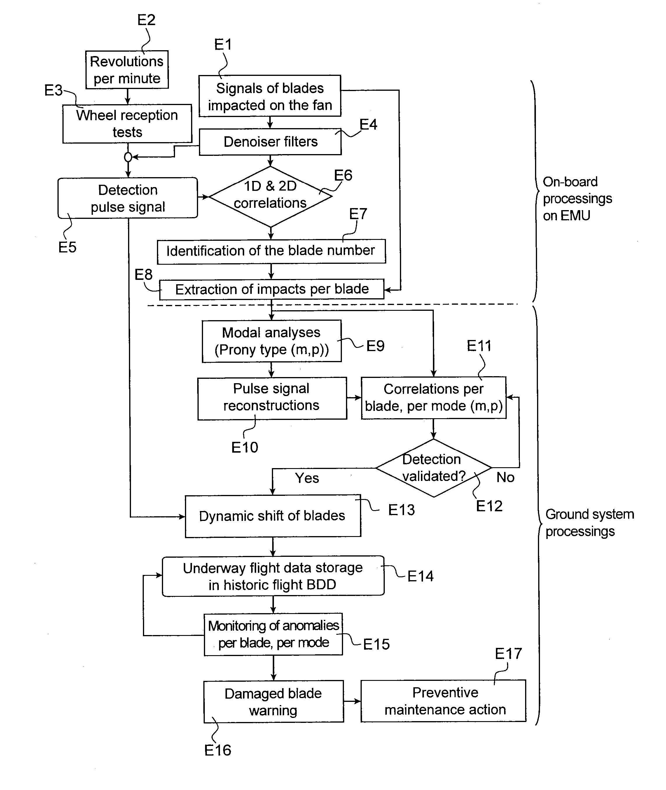
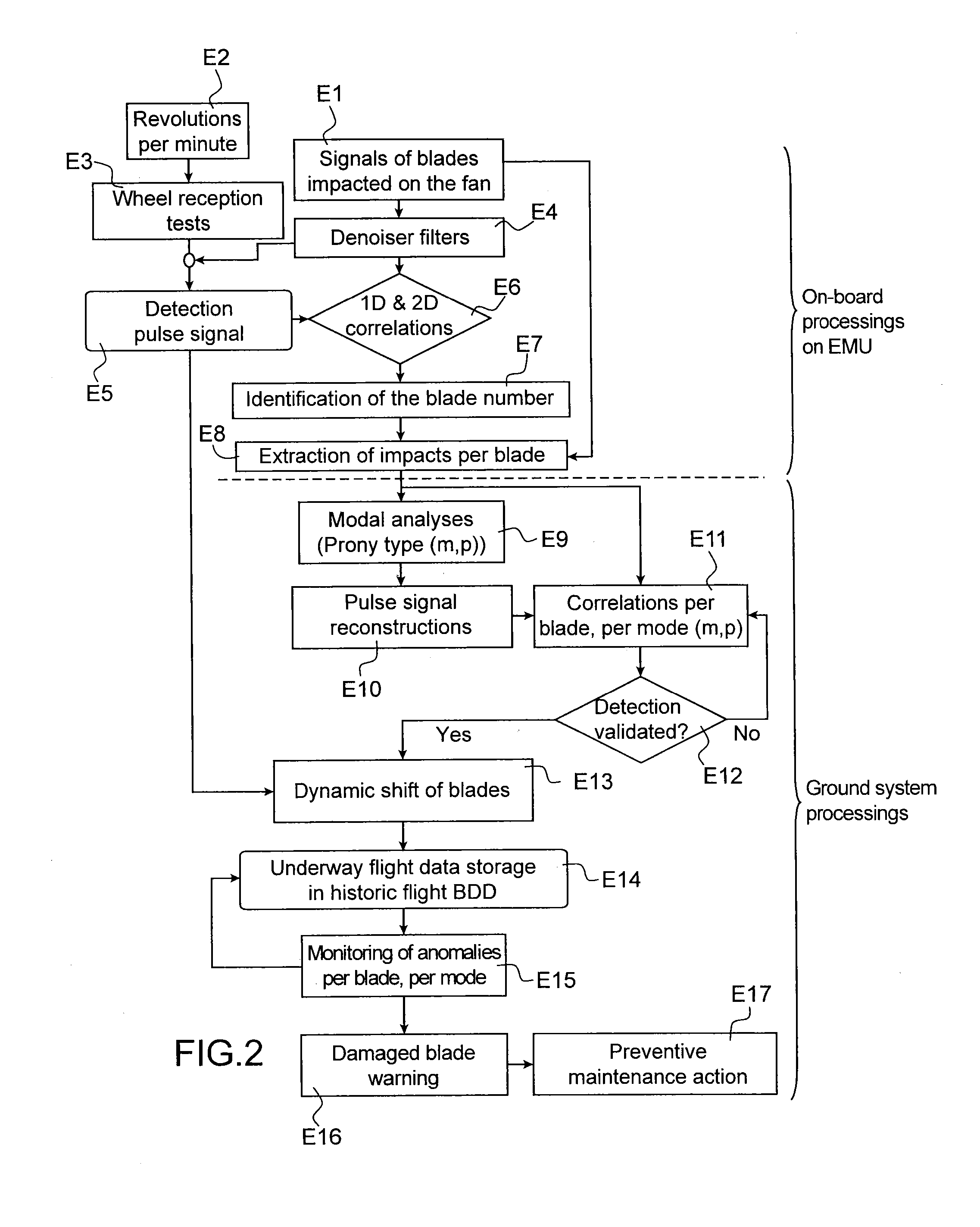
[0008]The present invention is defined by a method for detecting defects on an impeller wheel of an aircraft engine, comprising the following steps:[0009]acquisition of deflection signals representative of the deflections on the blades of said impeller wheel,[0010]identification of impact by correlations of each of said deflection signals with a detection pulse signal typical of an impact on a sound blade at the rotation frequency of the engine,[0011]extraction of the impact signals from among said deflection signals,[0012]application of a modal analysis to each of said impact signals to identify the modal parameters relative to each impacted blade, and[0013]monitoring the evolution of said modal parameters in order to detect defects on said blades.

[0014]By uniquely monitoring the impact signals, this method makes it possible to make more reliable the diagnostic by detecting structural defects not visible by inspection while reducing the computational load and while facilitating the...


PUM


Abstract

A method and an on-board system for detecting impact on an impeller wheel of an aircraft engine. Deflection signals representative of the deflections on the blades of the impeller wheel are acquired. Each of the deflection signals is correlated with a pulse signal typical of an impact on a sound blade at the rotation frequency of the engine, in order to identify impacts on the impeller wheel. The impact signals are extracted from among the deflection signals. The impact signals are transmitted to the ground in order that the signals are analysed to detect defects on the blades of the impeller wheel.

Description

TECHNICAL FIELD[0001]The present invention relates to the field of engine surveillance systems and, more particularly, the detection of defects on an impeller wheel of an aircraft engine.PRIOR ART[0002]An aircraft engine comprises several impeller wheels that are potentially exposed to undergoing impacts that can damage them and, consequently, affect the correct operation of the engine.[0003]In most cases, the impact is not noticed by the pilot during the flight and the finding on the blade is made during the control of the airplane just before taking off again. This constitutes the main cause of flight D&C (Delays and Cancellation).[0004]Methods exist for detecting impact on the blades, and particularly the blades of the fan. From these detections may be deduced impact breakdowns, which can help to issue warnings to bring about a visual or mechanical inspection of the blades.[0005]A visual inspection can only be carried out on blades that are visible, or which may be accessed via e...

Claims


Application Information

Patent Timeline
IPC IPC(8): G01N3/30
CPCG01N3/30F01D21/14F01D21/003F01D21/04F02C7/05G01H1/006G01M15/14G01N27/82
Inventor NICQ, GEOFFROYGEREZ, VALERIO
Owner SN DETUDE & DE CONSTR DE MOTEURS DAVIATION S N E C M A
Why Eureka
Try Eureka