Load control device, image forming apparatus, and method of controlling load

a technology of image forming apparatus and load control device, which is applied in the direction of electrographic process apparatus, instruments, electrographic process, etc., can solve the problems of large electric current flow and voltage drop in power supply voltage, and achieve the effect of controlling load more appropriately

Active Publication Date: 2013-09-12
SEIKO EPSON CORP
View PDF6 Cites 7 Cited by
  • Summary
  • Abstract
  • Description
  • Claims
  • Application Information

AI Technical Summary

Benefits of technology

The load control device described in this patent can control the load state more appropriately by switching the load state by one stage, which can reduce fluctuations in resistance value and minimize the change rate of electric current flowing through the load. This can help to suppress flickering or other problems that may occur in other devices. The image forming apparatus described in this patent also includes this load control device, which can provide better control over the load and minimize the impact on power supply voltage.

Problems solved by technology

Accordingly, there occurs a problem in that a voltage drop in the power supply voltage is increased and the large electric current flows.

Method used


Image

  • Load control device, image forming apparatus, and method of controlling load
  • Load control device, image forming apparatus, and method of controlling load
  • Load control device, image forming apparatus, and method of controlling load

Examples


Embodiment Construction

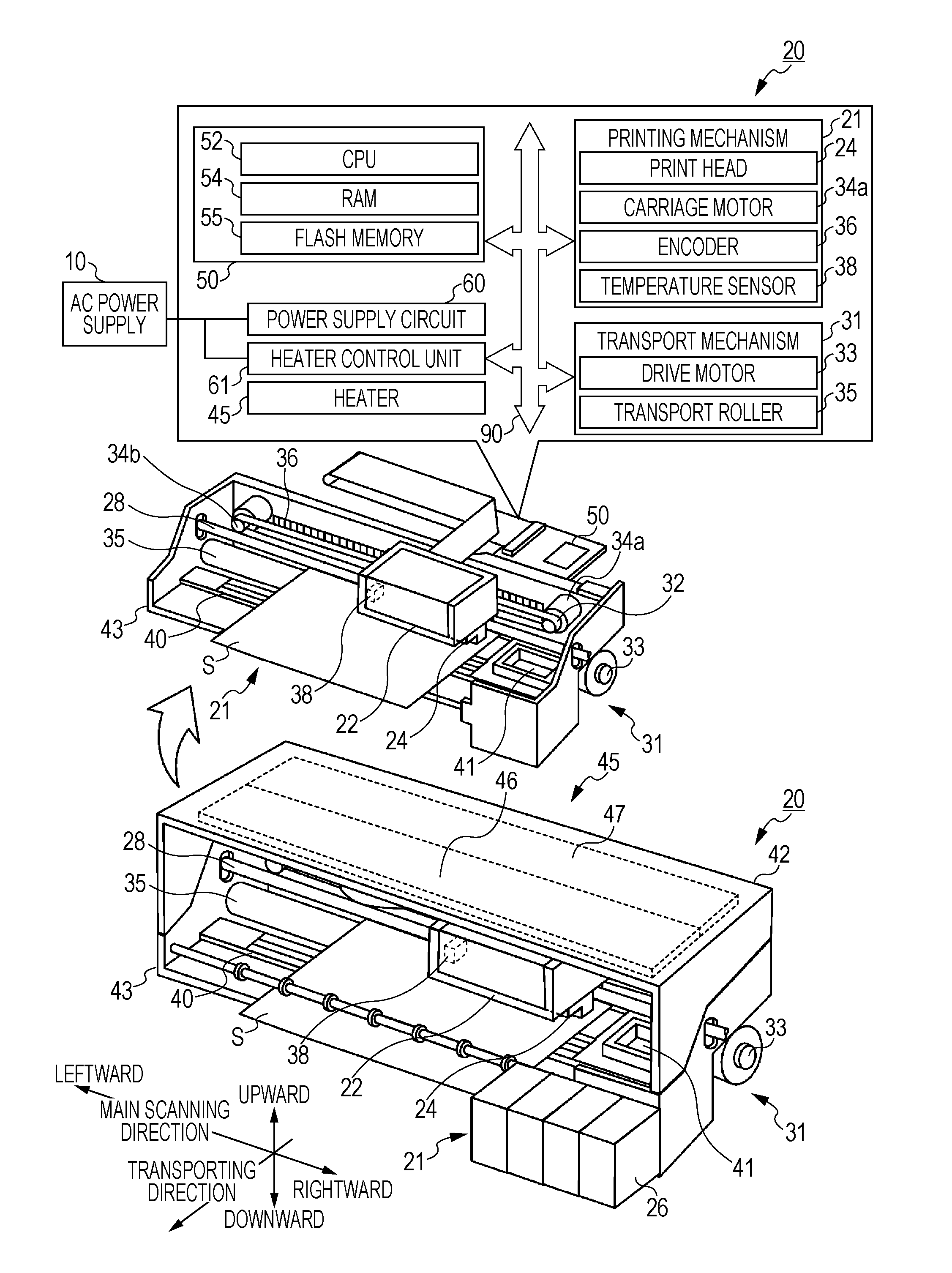
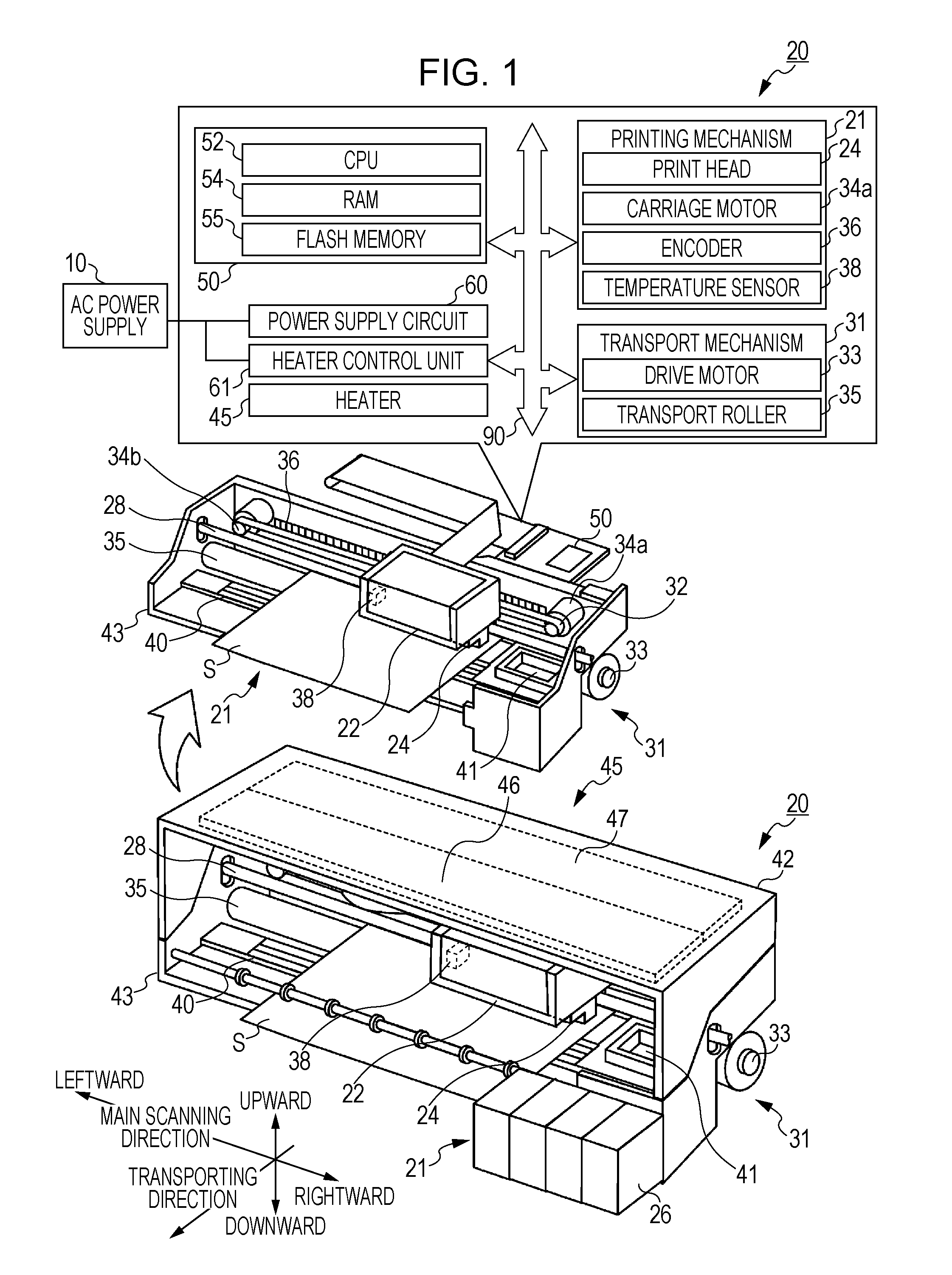
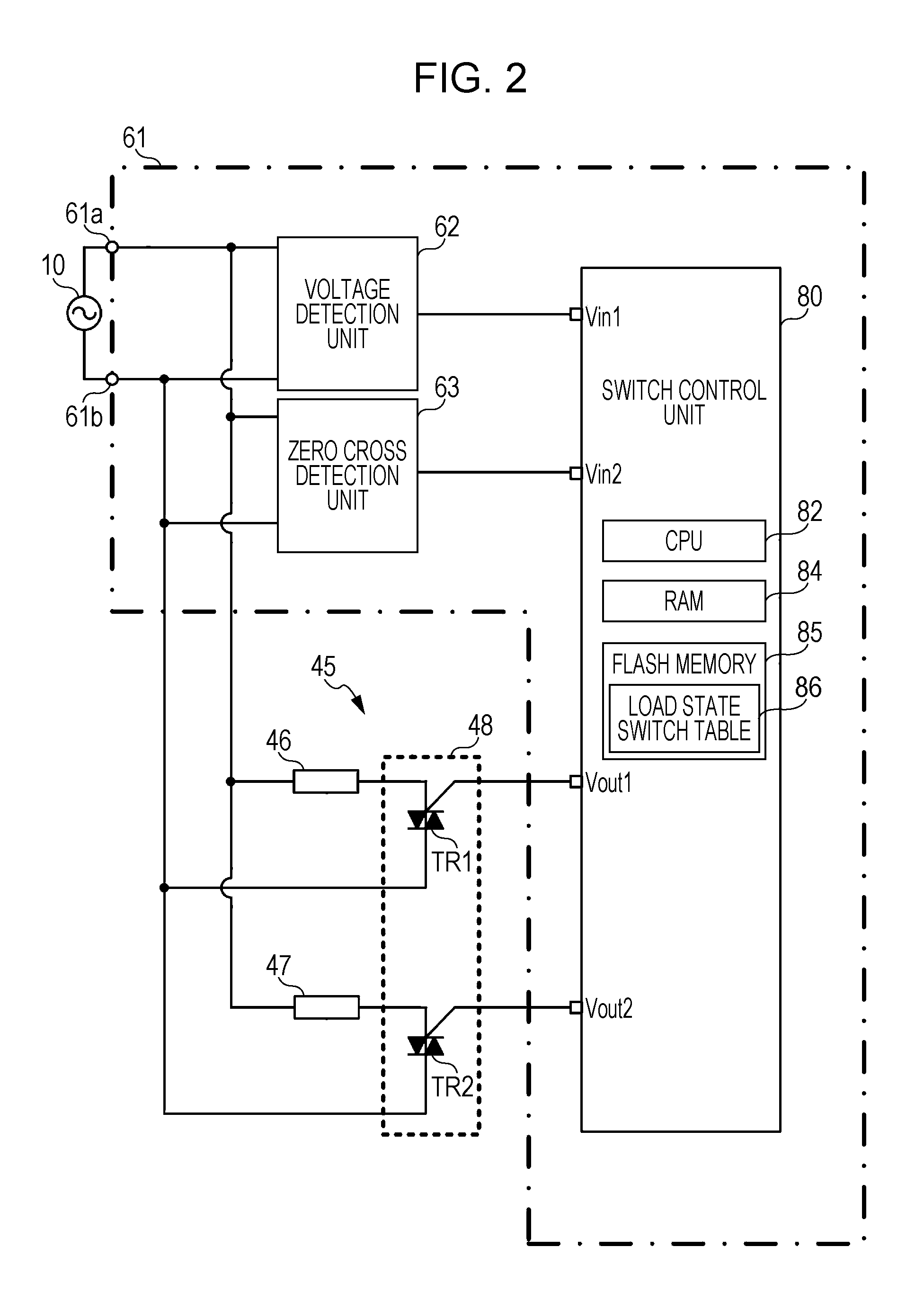
[0032]Next, an embodiment according to the aspect of the invention is described referring to the drawings. FIG. 1 is a configuration diagram illustrating an outline of a configuration of a printer 20 according to one embodiment of the invention. FIG. 2 is a circuit diagram illustrating a heater control unit 61. FIG. 1 also illustrates a configuration in which a cover 42 and a heater 45 are excluded. The printer 20 according to the present embodiment is configured as an ink jet type printer. As illustrated in FIG. 1, the printer 20 includes a print mechanism 21 that performs printing by ejecting an ink as a fluid from a print head 24 onto a print medium S (for example, a record paper sheet) that is transported to over a platen 40, and a transport mechanism 31 that transports the print medium S from a transport direction upper stream (inward from the drawing) to a transport direction lower stream (outward from the drawing) in such a manner that a drive motor 33 driving a transport rol...


PUM


Abstract

A switch control unit detects a power supply voltage of a heater detected by a voltage detection unit, and switch is performed on a load state of the heater in a range from a first load state to a fourth load state when the detected power supply voltage falls into a predetermined first domain. On the other hand, the switch is performed on the load state that ranges from the first load state to the third load state when the detected power supply voltage falls into a predetermined second domain that is higher in voltage than the first domain. That is, when the power supply voltage is in the second domain that is higher in voltage than the first domain, a limitation is imposed on the switch to the fourth load state where a combined resistance value is the lowest among the first and fourth load states.

Description

BACKGROUND[0001]1. Technical Field[0002]The present invention relates to a load control device, an image forming apparatus, and a method of controlling a load.[0003]2. Related Art[0004]In the related art, a load control device is known which performs, for example, switch that turns on and off a load, such as a heater used in an image forming apparatus. For example, it is disclosed in JP-A-2002-84736 that in a heater operating on electricity from an AC power supply in a power control apparatus, temperature control is performed on the heater by intermittent control that uses a zero cross control period during which the load turns on and an idle period during which the load turns off, between the zero cross points in a power supply wave pattern. In this manner, the load is controlled by performing the switch that turns the heater on and off using the zero cross point of the AC power supply, and for example inrush electric current at the time of turning on the heater may be suppressed, ...

Claims


Application Information

Patent Timeline
Patent Type & Authority Applications(United States)
IPC IPC(8): H02J3/00
CPCH02J3/00B41J29/393B41J29/38G03G15/11
Inventor UMEDA, ATSUSHI
Owner SEIKO EPSON CORP
Why Eureka
Try Eureka