
Magnetic resonance apparatus

a magnetic resonance and apparatus technology, applied in the field of magnetic resonance apparatus, can solve the problems of high noise level and unwanted gap between individuals, and achieve the effect of reducing and/or suppressing the propagation of sound waves, saving weight and housing units

Inactive Publication Date: 2013-09-12
SIEMENS HEALTHCARE GMBH
View PDF13 Cites 12 Cited by
  • Summary
  • Abstract
  • Description
  • Claims
  • Application Information

AI Technical Summary

Benefits of technology

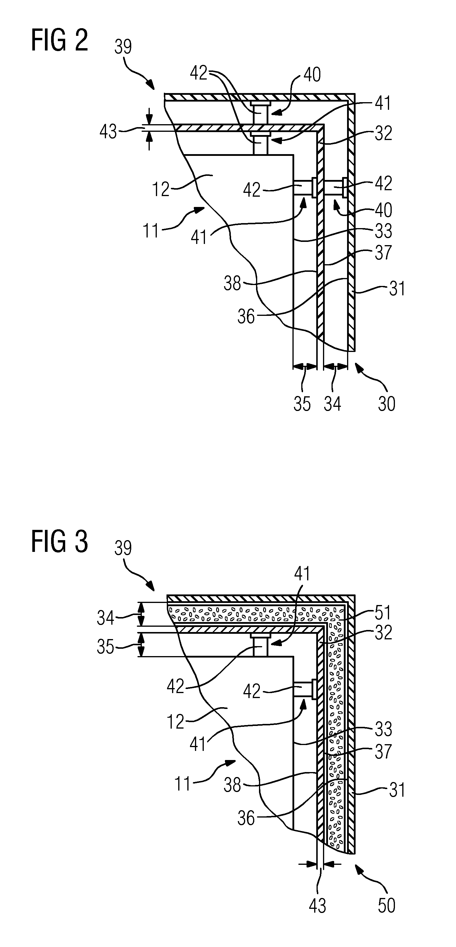
The patent proposes a housing unit for a magnetic device that creates noise decoupling around the magnet unit. This is achieved by using a closed covering that forms a gap-free and continuous covering around the magnet unit. The first and second housing shell units can be made of different materials to prevent resonance and unwanted resonance on the transmission of sound waves. The flexible housing shell unit can be made of a PVC material or an elastic material such as silicone or rubber to achieve screening of sound waves and decoupling of sound waves inside the housing unit. The housing unit also has at least one decoupling element, such as an elastic decoupling element or other materials that reduce or suppress transmission of sound waves. This results in a compact and light-weight housing unit.

Problems solved by technology

During operation, magnetic resonance apparatuses have high noise levels which can cause discomfort for a patient located in an imaging region of the magnetic resonance apparatus for the purposes of an examination.
These high noise levels are generated inside a magnet unit of the magnetic resonance apparatus.
This can give rise to an unwanted gap between the individual shell elements facilitating direct sound-wave propagation in the area surrounding the magnetic resonance apparatus.

Method used


Image

  • Magnetic resonance apparatus
  • Magnetic resonance apparatus
  • Magnetic resonance apparatus

Examples


Embodiment Construction

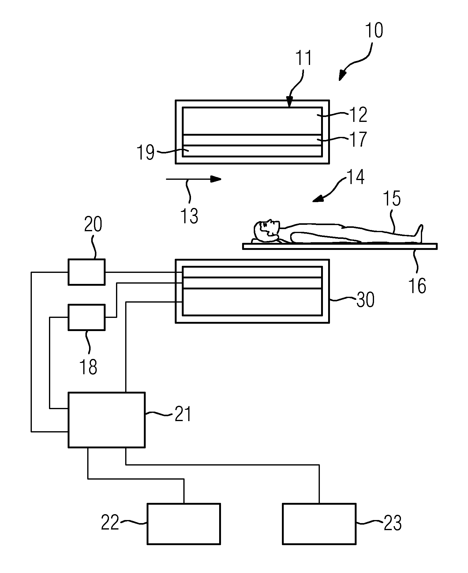
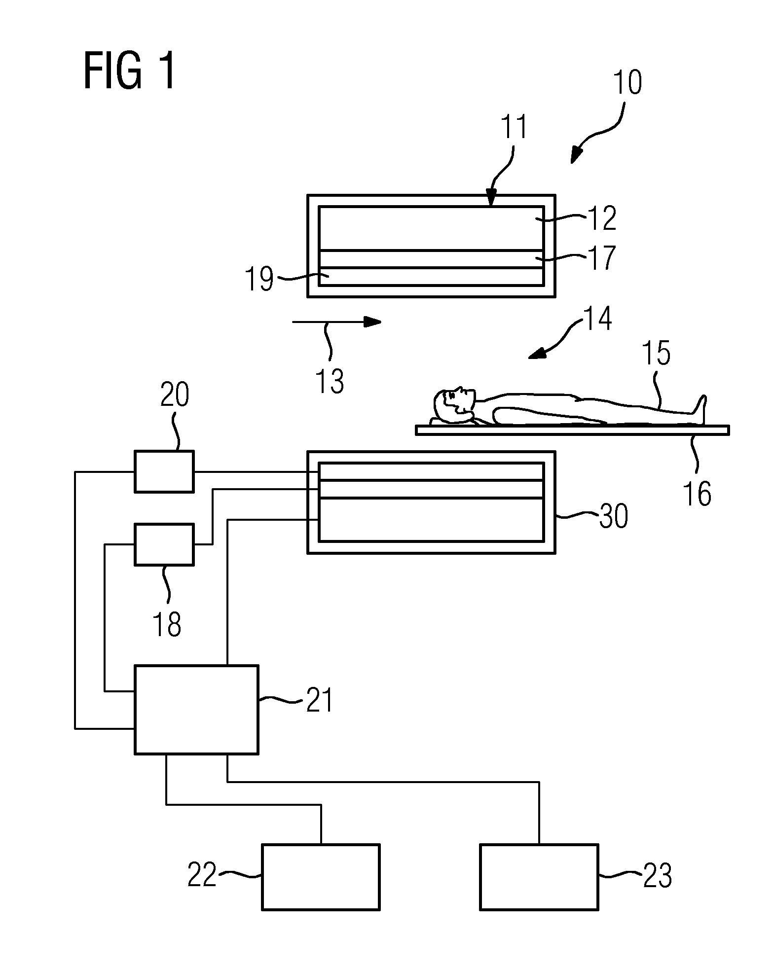
[0024]FIG. 1 is a schematic representation of a magnetic resonance apparatus 10 according to the application. The magnetic resonance apparatus 10 comprises a magnet unit 11 having a main magnet 12 for the generation of a strong and constant main magnetic field 13. In addition, the magnetic resonance apparatus 10 comprises a cylindrical imaging region 14 for accepting a patient 15, wherein the imaging region 14 is enclosed in a circumferential direction by the magnet unit 11. Alternatively to this, the imaging region 14 can also be U-shaped.

[0025]The patient 15 can be pushed into the imaging region 14 by a patient bed 16 in the magnetic resonance apparatus 10. For this, the patient bed 14 is arranged movably inside the magnetic resonance apparatus 10. The magnetic resonance apparatus 10 also comprises a housing unit 30 surrounding the magnet unit 11.

[0026]The magnet unit 11 also comprises a gradient coil 17 for generating magnetic field gradients used for spatial encoding during imag...


PUM


Abstract

A magnetic resonance apparatus is proposed. The magnetic resonance apparatus has a magnet unit and a housing unit surrounding the magnet unit. The housing unit has a first housing shell unit and a second housing shell unit. The second housing shell unit is arranged between the magnet unit and the first housing shell unit.

Description

CROSS REFERENCE TO RELATED APPLICATIONS[0001]This application claims priority of German application No. 10 2011 082 410.3 filed Sep. 09, 2011, which is incorporated by reference herein in its entirety.FIELD OF INVENTION[0002]The present application relates to a magnetic resonance apparatus having a magnet unit and a housing unit surrounding the magnet unit comprising a first housing shell unit.BACKGROUND OF INVENTION[0003]During operation, magnetic resonance apparatuses have high noise levels which can cause discomfort for a patient located in an imaging region of the magnetic resonance apparatus for the purposes of an examination. These high noise levels are generated inside a magnet unit of the magnetic resonance apparatus. The sound waves are transmitted by a gradient system in the magnet unit to a main magnet in the magnet unit. The noise is transmitted from this main magnet to a housing unit of the magnetic resonance apparatus and from there emitted into the area surrounding th...

Claims


Application Information

Patent Timeline
IPC IPC(8): G01R33/38
CPCG01R33/38G01R33/28
Inventor DIETZ, PETERMACIEJEWSKI, BERNDSTEIN, ANNETTE
Owner SIEMENS HEALTHCARE GMBH
Learn More